0 mechanical/electrical description, 1 mechanical description, 2 electrical description – Rockwell Automation 61C615 RTD Termination Panel User Manual
Page 9
2Ć1
2.0 MECHANICAL/ELECTRICAL
DESCRIPTION
The following is a description of the termination connectors and
electrical characteristics of the fieldconnections.
2.1
Mechanical Description
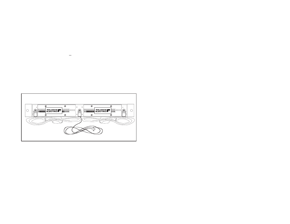
The 61C615 is a 19" rackĆmountable termination panel that includes
two 6Ćfoot, 50Ćwire twistedpair flat cables anda 6Ćfoot power cable. A
separately mounted+15 volt power supply is provided by the user.
Refer to figure 2.1. Panel dimensions are listed in Appendix A.
When the panel is viewedfrom the front, the flat cable on the right
side of the termination panel (TB2) is for analog inputs 8Ć15. It
connects to the bottom connector on the 61C613. The flat cable on
the left side of the termination panel (TB1) is for analog inputs 0Ć7. It
connects to the middle connector on the 61C613. The top connector
on the 61C613 module is not used.
The termination panel includes 64 clampĆtype screw terminals for
terminating fieldsignals. A clear plastic shieldis providedas a cover
for the terminal strips.
Figure 2.1Ć 61C615 Termination Panel
2.2
Electrical Description
The RTD termination panel is usedto linearize andpower 100 ohm
platinum Resistance Temperature Detectors usedwith the 61C613
analog input module. The resistance change of the RTD with
temperature is sensedby using the RTD as the external 4th arm of a
bridge. The termination panel contains the internal portions of the
bridge as well as the bridge excitation supply. See figure 2.2.