3 field calibration – Rockwell Automation 61C615 RTD Termination Panel User Manual
Page 12
3Ć2
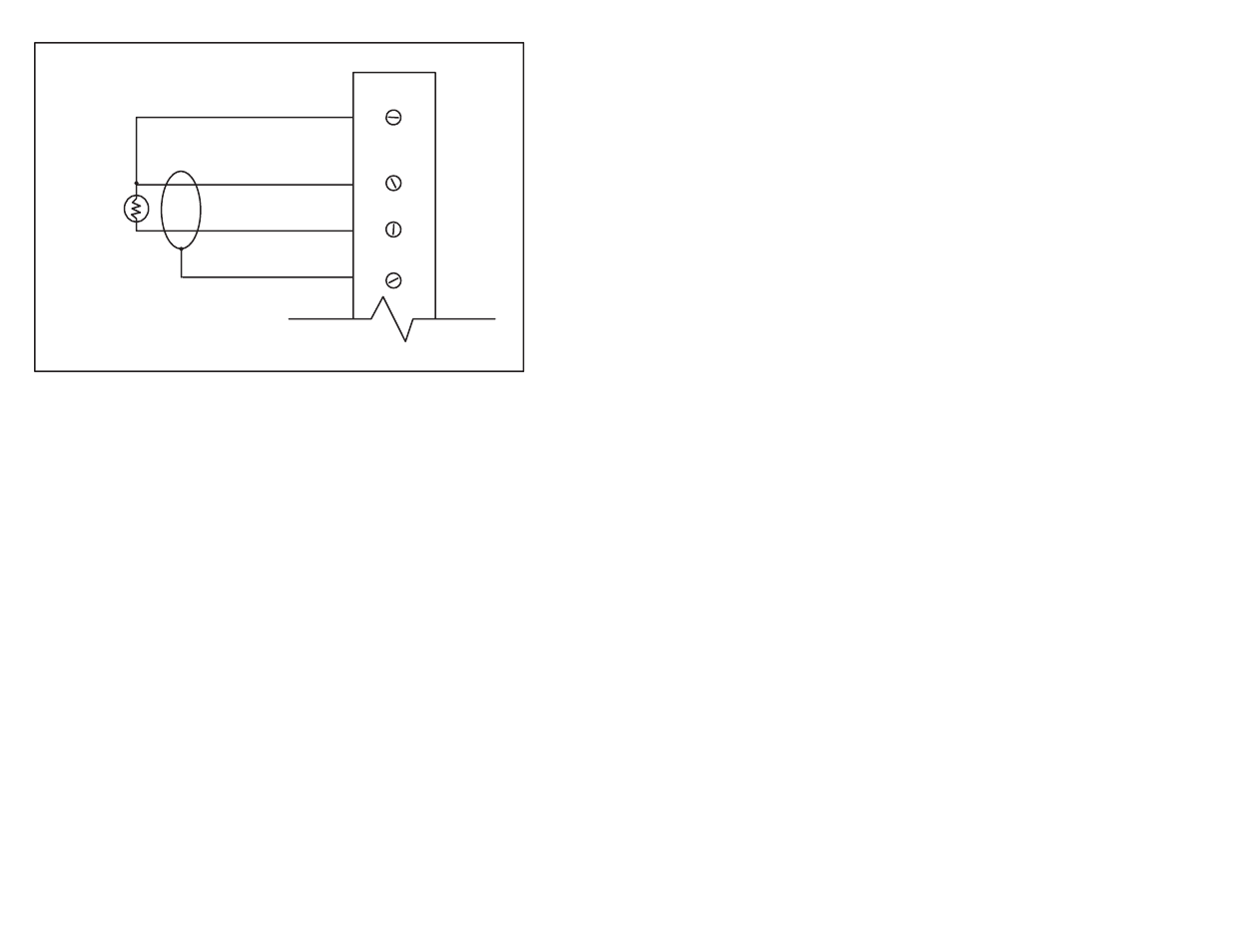
3 WIRE
100 OHM
RTD
4
3
2
1
SENSE (LOW0
LOW R
HIGH R (GND)
SHIELD
Figure 3.1Ć Typical Field Signal Connections
Step 6.
Connect the 50Ćpin flat cables to their corresponding
connector on the analog input module (61C613). Attach
the cables by aligning the triangle marks on the cable end
and the board socket. Input channels 0Ć7 (TB1) use the
middle connector on the input module. Input channels
8Ć15 (TB2) use the bottom connector. If the rack contains
more than one analog input module, make certain that the
connectors are the proper ones for this module.
Step 7.
Turn on power to the system.
Step 8.
Verify the installation. Refer to the instruction manual for
the 16 Channel Analog Input Module (JĆ3613Ć1).
3.3
Field Calibration
The termination panel is adjusted for European curve RTDs (alpha
temperature coefficient of 0.00385 ohms/ohm/degree C) and
includes an allowance for 0.1 ohm lead resistance. For lead
resistance greater than 0.1 ohm, the following procedure can be
used to calibrate the input for maximum accuracy:
1. The offset adjustment should not normally need further field
adjustment. If it becomes necessary, substitute a precision 100
ohm resistor in place of the RTD and adjust the offset
potentiometer for an output of zero volts. The offset
potentiometers are located at the back of the panel. Each
channel has a separate offset adjustment labeled OS".
2. Adjust the gain potentiometer so that total bridge voltage is
256.3mV across the 100 ohm resistor. The gain potentiometers
are located at the back of the panel. Each channel has a
separate gain adjustment labeled GN".