Input/output mapping, Set input filter times, Input/output mapping set input filter times – Rockwell Automation 1797-IBN16 FLEX Ex NAMUR Input Module User Manual
Page 11: Flex ex namur input module 11 publication
FLEX Ex NAMUR Input Module 11
Publication
1797-5.7 - March 2010
Input/Output Mapping
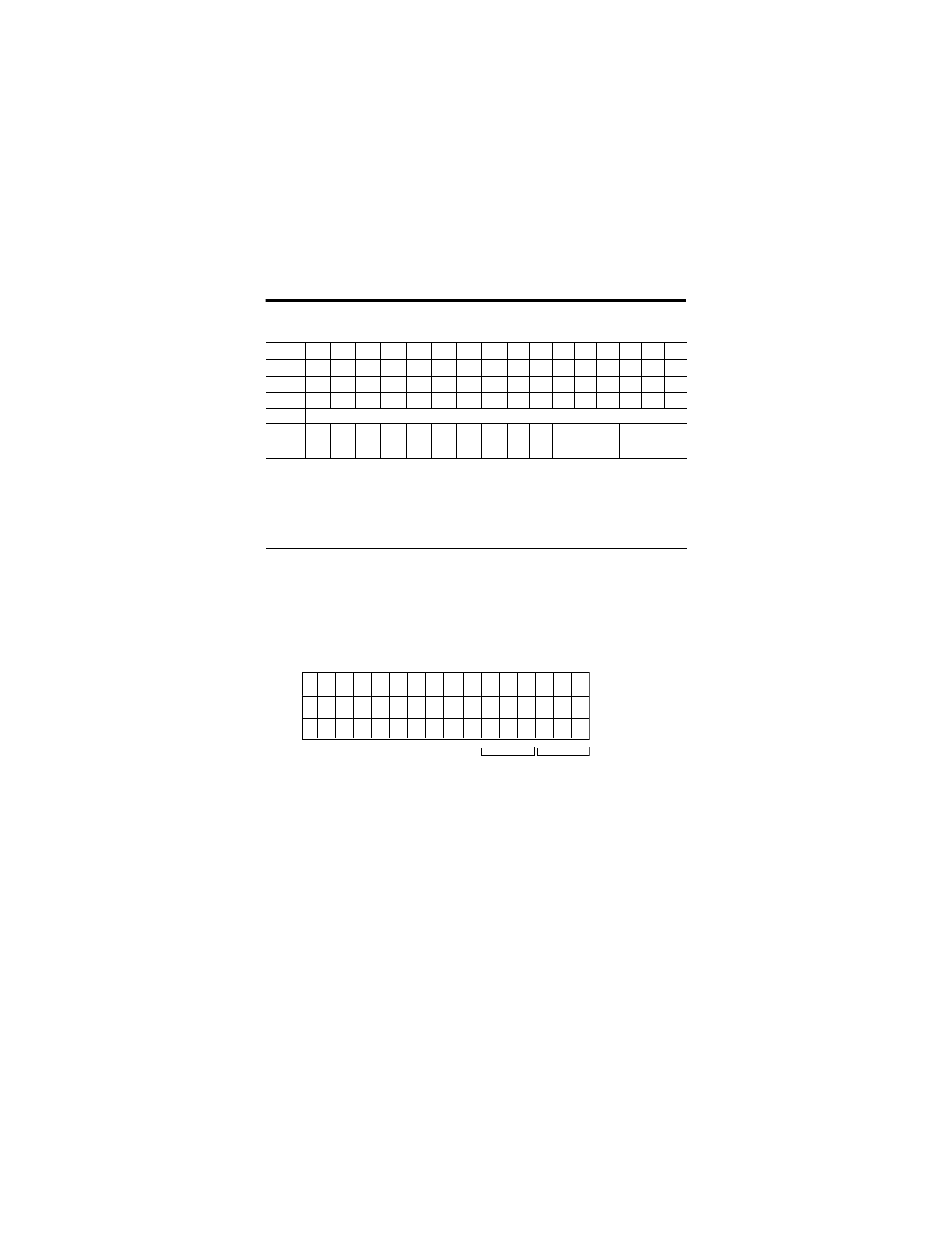
Set Input Filter Times
You can select the input filter time constant for each group of channels
(channels 00 to 11 or channels 12 to 15).
For example, to set a filter time constant of 5 ms for a dc input module, set
bits 05, 04, 03, 02, 01, and 00 as shown below.
Dec. Bit
15
14
13
12
11
10
09
08
07
06
05
04
03
02
01
00
Oct. Bit
17
16
15
14
13
12
11
10
07
06
05
04
03
02
01
00
Read 0
I15
I14
I13
I12
I11
I10
I9
I8
I7
I6
I5
I4
I3
I2
I1
I0
Read 1
F15
F14
F13
F12
F11
F10
F9
F8
F7
F6
F5
F4
F3
F2
F1
F0
Read 1
Input 15 Counter
Write 0
CF
CR
FC
Input Filter - Ch
12…15
Input/Alarm
Filter - Ch
0…11
Where:I = Input
F = Fault Alarm for an individual channel
CF = Counter Fast - Filter time constant or bypass, depending on setting (when input 15 is in counter mode) -
0 = normal, 1 = fast
CR = Counter Reset- Resets the counter value in read word 1 when input 15 is in counter mode.
0 = normal, 1 = reset
FC = Fault mode or Counter mode - determines content of read word 1 (counter value of input 15, or
fault data of individual channel). 0 = counter, 1 = fault data - wire off or short
circuit detect
40154
FT = 12 to 15
(14 to 17)
Dec.
(Octal)
O:010
15 14 13
12
11
10 09
08
07
06
05 04
03
02 01
00
17 16 15
14
13
12 11
10
07
06
05 04
03
02 01
00
1
0
0
1
0
0
FT = 00 to 11
(00 to 13)
=44 Octal
or 36 Decimal