2090-cthp8 terminator schematic and pinout – Rockwell Automation 2090-CTHP8 Kinetix 6000M Hybrid Power Terminator Installation Instructions User Manual
Page 5
Kinetix 6000M Hybrid Terminator 5
Publication 2090-IN035B-EN-P - March 2012
1. Verify power to the IPIM module is removed before making any connections or
disconnecting any components of the system.
2. Attach the hybrid terminator to the power-out connector on the last IDM unit in the
system.
3. Tighten the M23 connector approximately 45° to fully seat the contacts and secure the
connection.
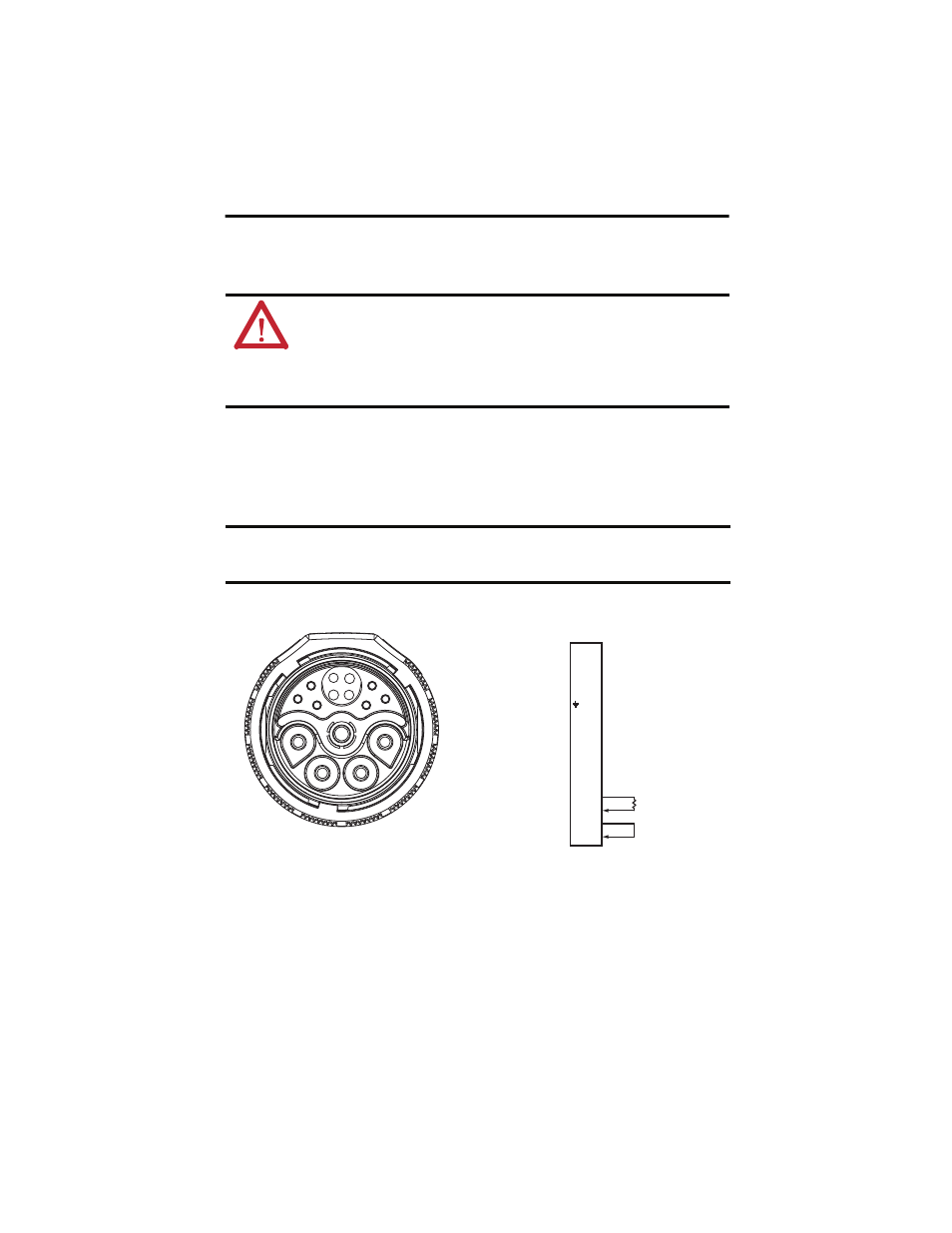
2090-CTHP8 Terminator Schematic and Pinout
ATTENTION: Arcing or unexpected motion can occur if cables are connected or disconnected while
power is applied to the IDM system. Before working on an IDM system, disconnect power and wait
the full time interval as indicated in the warning on the IPIM module or verify the DC bus voltage at
the IPIM module measures less than 50V DC.
Failure to observe this precaution could result in severe bodily injury or loss of life, and damage to
the product will occur.
IMPORTANT
The internal O-ring is self-conforming and requires a short period between each
connect/disconnect cycle to expand to full size. Allow at least one minute for the O-ring to
expand before reconnecting the hybrid terminator.
A
B
C
D
GND
1
2
3
4
5
6
7
8
9
10
D
A
B
C
GND
9
8
7
10
1
6
5
4
3
2
Male Plug
100
Ω
CN+
CN -
SYS OK +
SYS OK -