Schematics and connector pinouts for cables, 2090-cpbm7df-xxafxx cables, 2090-cpwm7df-xxafxx cables – Rockwell Automation 2090-CPBM7DF-08AF Continuous-flex Power Cables with SpeedTec DIN Connector Installation Instruction User Manual
Page 6
6 Continuous-flex Power and Brake Cables with SpeedTec DIN Connector
Publication 2090-IN026B-EN-P - January 2011
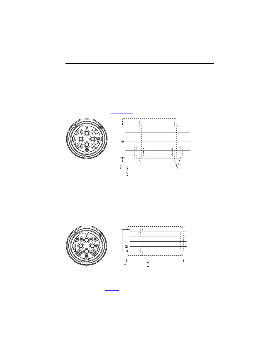
Schematics and Connector Pinouts for Cables
Wire colors and connector pinouts necessary to connect the cable to a servo system are shown in
the schematics.
2090-CPBM7DF-xxAFxx Cables
This cable is available in several wire gauges and lengths. Refer to the Kinetix Motion Control
Selection Guide, publicat
for this information and additional specifications.
(1)
Wire gauge and connector keying varies based on motor and power requirements. Refer to the Kinetix Motion Control
Selection Guide, publication
, for additional information.
2090-CPWM7DF-xxAFxx Cables
This cable is available in several wire gauges and lengths. Refer to the Kinetix Motion Control
Selection Guide, publicat
for this information and additional specifications.
(1)
Wire gauge and connector keying varies based on motor and power requirements. Refer to the Kinetix Motion Control
Selection Guide, publication
, for additional information.
U
V
W
GND
MBRK
+
MBRK
-
U
V
W
+
-
(1)
Brown
Blue
Green/Yellow
Black
(1)
(1)
18 AWG White
18 AWG Black
Shield
(1)
Twisted Wire Pair
360° shield-to-ground
connections required.
To
Motor
Connector
Backshell
Shielded 360°
Shield
Wire Connection
To
Drive
(1)
U
V
W
U
V
W
GND
Brown
Black
Blue
Green/Yellow
(1)
(1)
(1)
Twisted Wire Pair
360° shield-
to-ground
connections
required.
To
Motor
Connector
Backshell
Shielded 360°
Wire Connection
To
Drive