Rockwell Automation 2090-CPBM7DF-08AF Continuous-flex Power Cables with SpeedTec DIN Connector Installation Instruction User Manual
Page 5
Continuous-flex Power and Brake Cables with SpeedTec DIN Connector 5
Publication 2090-IN026B-EN-P - January 2011
3. Observe these restrictions on the flex zone and installation areas when installing the
cable:
•
The flex zone is the area in which the cable can repeatedly flex up to its specified
bend radius.
•
Installation areas require rigid mounting to prevent the cable from flexing where it
connects to other components.
4. Identify each connection on a cable by attaching a label around the outer insulation of
each wire adjacent to the drive connection.
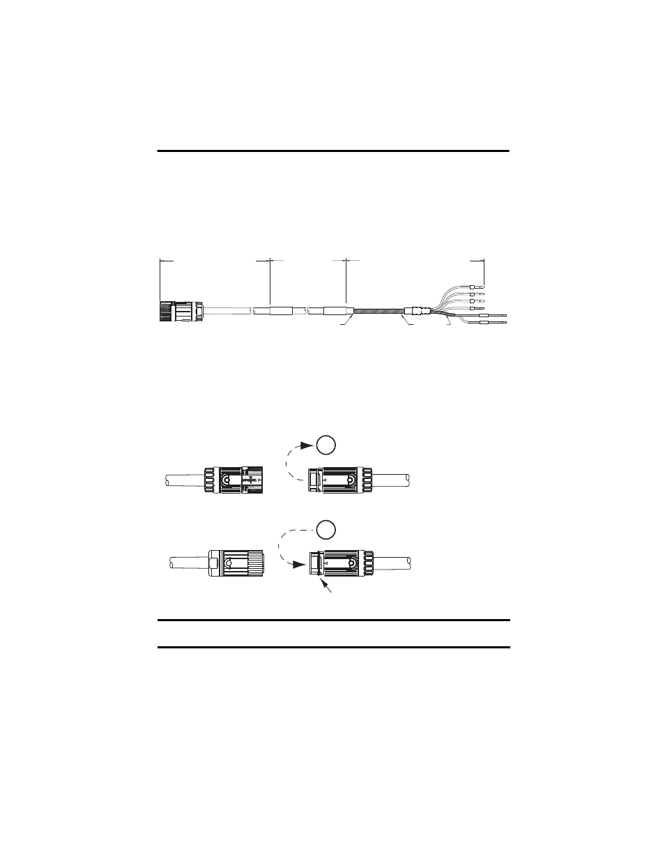
5. Remove the O-ring on the motor receptacle when using a cable with a SpeedTec plug.
The type of plug on the cable determines whether an O-ring is required on the
receptacle.
IMPORTANT
The O-ring dampens the effects of vibration at the cable-to-motor connection.
This creates a more secure connection for a cable with a threaded plug.
U
Y
W
PE
WHITE
BLACK
MBRK+
MBRK-
Feature Offset
Minimum of 1x Cable Diameter
Flex Zone
2090-CPBM7DF-xxAFxx Shown
Installation Area
300 mm (12 in.)
approx.
Installation Area
300 mm (12 in.)
approx.
Exposed
Shields
SpeedTec Plug
Threaded Plug
Remove O-ring when mating with a
SpeedTec plug.
Install O-ring when mating with a
threaded plug.
O-ring in Groove
If an O-ring is installed, a SpeedTec plug will not engage with the receptacle.