Removing cmc cabinet access plates – Rockwell Automation 7000 PowerFlex AC Drive with Direct-to-Drive Technology User Manual
Page 7
Re-installing a Separately Shipped Common Mode Choke (CMC) • Installation Instructions
3
Publication 7000-IN003B-EN-P – June 2013
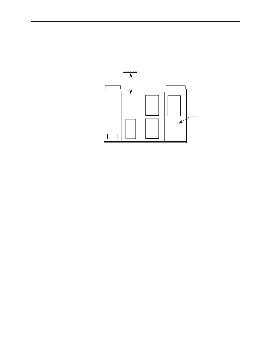
Refer to the Dimensional Drawings supplied with the VFD. The cabinet
section that houses the CMC is designated on the drawing as “LINK”
(right-hand side of the overall VFD Enclosure – looking from the front).
A typical example is shown in Figure 1.
Capacitors
Line
Reactor
LV Control
and
Connection
Inverter
Rectifier
Fan
Link
CMC
Cabinet
Section
Figure 1 – Typical Dimension Drawing excerpt
The rear of the CMC Cabinet Section has three cover plates (top to
bottom). Remove the taptite screws that secure the center plate first; then
also remove the top and bottom plates. Please note that there are small
seams on the top and bottom horizontal outer edges of these plates that
are sealed with silicone. A small tube of silicone is included in a cardboard
box typically located behind the black low voltage compartment door.
This can be used to reseal these seams after the CMC is reinstalled and
the cover plates replaced.
Open the front door of the CMC Cabinet Section by turning the three
hex key door latches counter-clockwise (located along the right vertical
edge of the door). Behind the door is a large interior white metal barrier
plate (see Figure 2). Remove the bolts (the nuts behind are held captive)
around the periphery of this plate that secure this barrier, to gain access to
the front of the CMC compartment located behind the barrier.
Ensure reinstallation of this barrier after the CMC is installed.
Removing CMC Cabinet
Access Plates