Rockwell Automation 9000 Series 9000 On/Off and Timing Photoelectric Sensors User Manual
Page 6
6
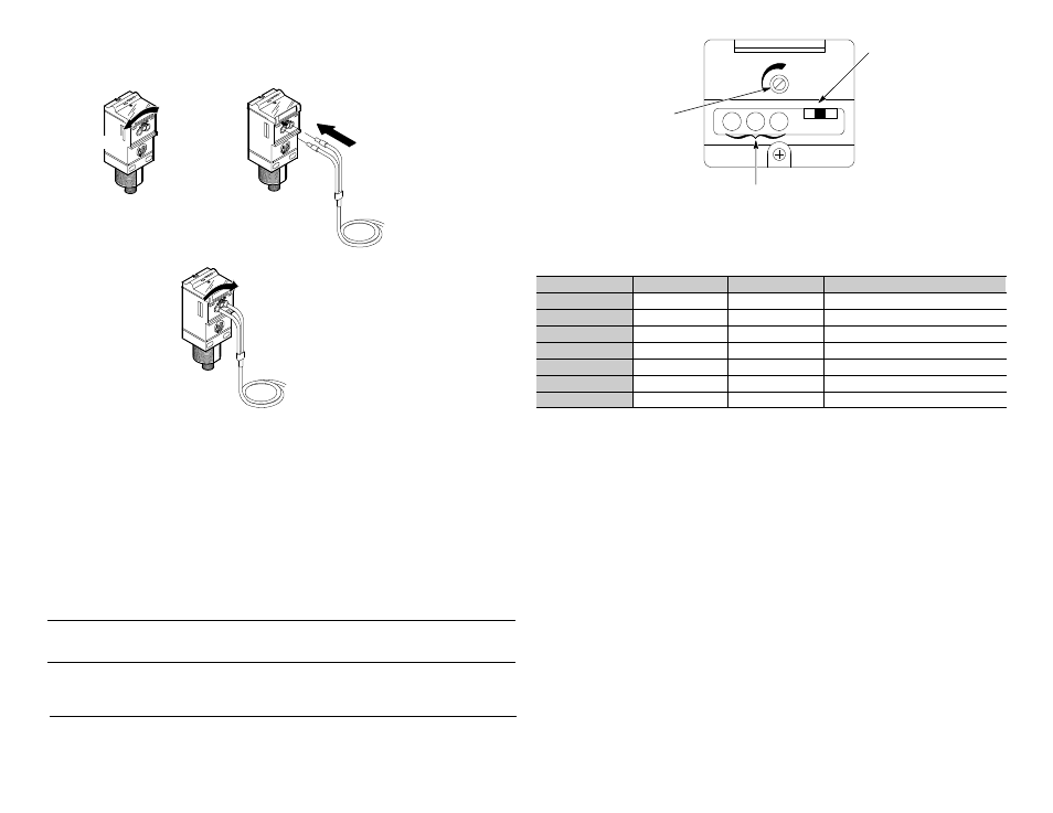
Installing Fiber Optic Cables (42GxF--9xxx versions only)
1. Ensure that the fiber optic cable locking lever on the sensor is in the UNLOCKED position.
2. Insert the fiber optic cable until the internal clip mechanism is engaged.
3. Rotate the locking lever to the LOCK position.
4. Mount the fiber optic cable sensing tip end as appropriate.
1. Set lever to UNLOCK position.
2. Insert fibers.
UNLOCK
LOCK
3. Rotate lever to LOCK position.
Wiring the Sensor
The Series 9000 photoelectric sensor is available in one of three different connection types as identified on page 1.
Rockwell Automation recommends the use of the 889 Series of cordsets and patchcords on the quick disconnect models.
All external wiring should conform to the National Electrical Code and all applicable local codes.
Configuring the Sensor—All models except 42GSP--9000
Use the information below to align and configure the sensor.
User Interface
Using an instrument screwdriver, open the top cover of the sensor to gain access to the user interface panel. This panel
contains a single-turn sensitivity adjustment knob, a two-position mode selector switch, along with three LED status
indicators. Using the same screwdriver, the sensitivity can be increased (clockwise) or decreased (counterclockwise) to
meet the application requirements. The factory default setting for all versions is maximum sensitivity.
IMPORTANT:Damage to single-turn sensitivity adjustment knob will occur if
turned beyond min/max steps.
IMPORTANT After initial sensor configuration ensure that the user interface
cover is closed tightly to maintain specified environmental
ratings!
42GRx—Top View Detail
LED Status Indicators
Light/Dark
Operate Switch
Sensitivity Adjustment
The Series 9000 photoelectric sensor also contains a two-position selector switch. This switch is used to select either
light- or dark-operate mode of the sensor. In light-operate mode, the sensor output will turn ON when light is being
reflected back to it (reflector for retroreflective, source for transmitted beam, or target for diffuse). In dark-operate mode,
the sensor output will turn OFF when no light is being reflected back to it.
The table below describes the function of the three LED status indicators.
Label
Color
State
Status
Output
Green
OFF
Output de-energized, SCP active
ON
Output energized
Margin
Red
OFF
Margin < 2.5
ON
Margin >2.5
Flashing
Output SCP active
Power
Yellow
OFF
Sensor not powered
ON
Sensor powered
Sensor Alignment
The red LED indicator is an alignment aid which indicates that a margin of 2.5X has been reached. This means that the
sensor is receiving at least 2.5 times the signal strength back from the target needed to trigger an output signal. In
general, it is desirable to have a higher margin to help overcome any deteriorating environmental conditions, i.e. dust
buildup on the sensor’s lens. When aligning the sensor, the best performance can be obtained if this margin indicator is
illuminated with the target in place. It is recommended to leave the sensitivity at its default maximum setting and change it
only when necessary.
Transmitted Beam Versions
1. Visually align the emitter and receiver units (emitter and receiver fibers) until the green output LED turns ON (with
light-operate mode) or turns OFF (with dark-operate mode).
2. To be certain that the beam is centered, it is required to sweep the emitter or receiver in the horizontal and vertical
plane and determine at what position the output indicator goes ON and then goes OFF. Set the sensor (or fiber optics)
midway between both positions. The red margin LED should also be ON when the beam is unbroken.