Connect the cordset to the flexarmor module – Rockwell Automation 1798-IB8 FlexArmor 24V dc Sinking Input Modules User Manual
Page 5
FlexArmor 24V dc Sinking Input Modules 5
Publication 1798-IN001A-EN-P - January 2001
Connect the Cordset to the FlexArmor Module
These modules use 5 pin micro (12mm) style PCB mounted
connectors.
Four micro caps cover the I/O connectors on both modules. Remove
the caps and connect your cables to the appropriate ports. Keep the
caps in place on any unused connector to maintain the IP67 rating.
Refer to publication no. 889-CP0021A-EN-P for compatible Rockwell
Automation cables and cordsets.
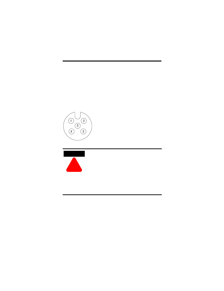
A pinout diagram for the connectors is shown below.
ATTENTION
!
•
Make sure all connectors and caps are
securely tightened to properly seal the
connections against leaks and maintain IP67
requirements.
•
For maximum noise immunity, input and
output cable return wires must be properly
terminated. When inputs and outputs are
connected in loopback, return wires should
be connected together.
•
I/O cable length should be less than 30
meters.
42652
Input Micro-Connector
(View into Socket)
Pin 1 Sensor Power
Pin 2 Input B (IB8 module only)
Pin 3 Sensor Common
Pin 4 Input A
Pin 5 Not Used