Step 4. ordering a new data name plate – Rockwell Automation 2364, 2364F Regenerative DC Bus Supply Unit (RGU) Upgrade Kit User Manual
Page 9
Regenerative DC Bus Supply Unit (RGU) Upgrade Kit
9
3. Locate the twisted red/black pair of wires that connect the capacitor
bank assembly (located behind the door) to J10 on the gate driver board.
Cut the pair of wires at both sides of the label on the wires (close to the
middle of the harness). The label on the twisted pair of wires reads
“74101-495-54.”
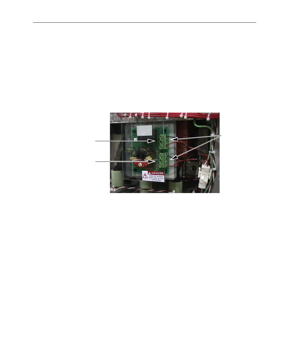
4. Strip the cut ends of each wire about ¼ inch (7 mm) and connect them
to the terminal blocks as shown in Figure 10 below. The wires from the
capacitor bank connect to the bottom terminal block (TB1) on the
power supply filter board. TB1-1 is plus (red wire) and TB1-3 is
negative (black wire). The wires from J10 connect to the top terminal
block (TB2). TB2-1 is plus (red wire) and TB2-3 is negative (black
wire). See Figure 10.
Figure 10
5. Replace the clear lexan cover (P/N 192425) to the filter board assembly.
Step 4. Ordering a New
Data Name Plate
Contact the factory with the information from the old Data Name Plate. A
new Data Name Plate will be issued. Attach the new Data Name Plate to the
bottom of the Module Door.
4. Connect twisted
red and black wires to
power supply filter
board terminal blocks
as shown
TB2
TB1