Replace a communication module, Back cover – Rockwell Automation 2711P-RNxxx Communication Modules Installation Instructions User Manual
Page 4
Rockwell Automation Publication 2711P-IN003E-EN-P - November 2012
PN-172825
Supersedes Publication 2711P-IN003D-EN-P - June 2010
Copyright © 2012 Rockwell Automation, Inc. All rights reserved. Printed in the U.S.A.
Allen-Bradley, DH+, FactoryTalk, PanelView, Rockwell Software, and Rockwell Automation are trademarks of Rockwell Automation, Inc.
Trademarks not belonging to Rockwell Automation are property of their respective companies.
Rockwell Otomasyon Ticaret A.Ş., Kar Plaza İş Merkezi E Blok Kat:6 34752 İçerenköy, İstanbul, Tel: +90 (216) 5698400
5. Push down on the communication module until the connectors are seated.
6. Tighten the four screws that
secure the communication
module to the logic module
to a torque of 0.58 N•m
(5…7 lb•in).
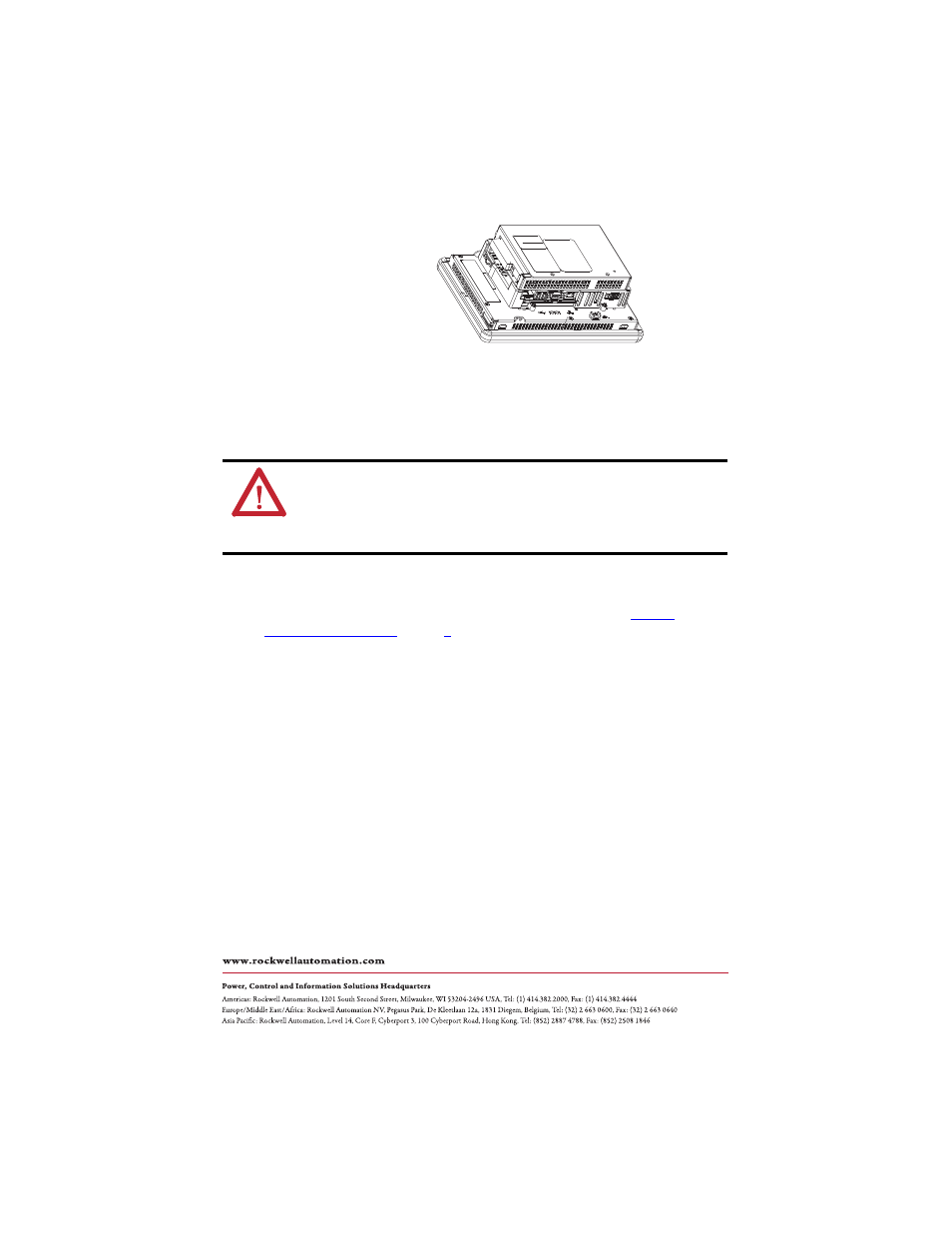
Replace a Communication Module
Follow these steps to replace a communication module.
1. Disconnect power from the terminal.
2. Disconnect communication cables from the module.
3. Remove the four screws that secure the communication module.
4. Carefully lift the communication module away from the logic module.
5. Install the new communication module by following steps 3…6 under
WARNING: Explosion Hazard
Do not connect or disconnect any communication cable with power applied to this device or
any device on a network. An electrical arc could cause an explosion in hazardous location
installations. Be sure power is removed or the area is known to be nonhazardous before
proceeding.