Junction box cable diagram, X1/k3, X2/k4 – Rockwell Automation 2727-MREX1 MobileView Junction Box Cable Installation Instructions User Manual
Page 4: Pin 1, 24v dc, Junction box cable
4 MobileView Junction Box Cable
Publication 2727-IN005C-MU-P
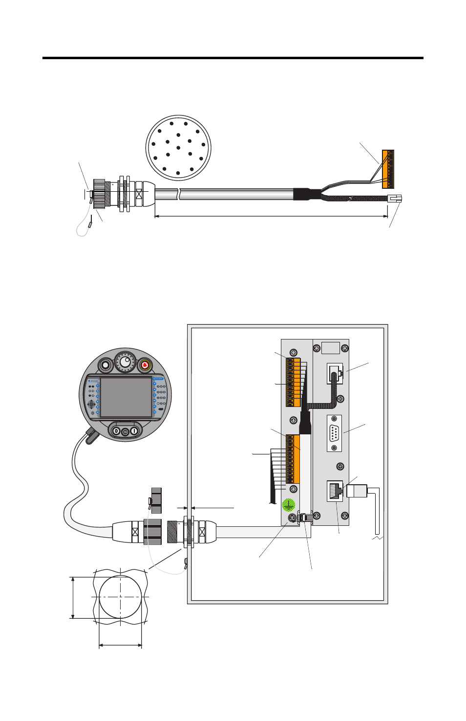
Junction Box Cable Diagram
Connecting the MobileView MT750 or G750 Terminal to Junction Box
The following illustration shows how the Junction Box Cable (2727-MREX1) is used
to connect the MobileView Terminal to the Junction Box (2727-MRJB1).
1
2
3
4
5
6
7
8
9
10
11
12
13
14
15
16
17
K3, 12-pin connector for
terminal block X1 at Junction Box.
K2, 8-pin RJ-45 jack
(Ethernet) for S1 at Junction Box
Dust cap provides
protection when
MobileView is not
connected.
17-pin circular jack
mounts to enclosure.
2 meter (6.5 foot)
X1/K3
24V D C
ON LY
TER M IN AL IN
R S422 O U T
ETH ER N ET O U T
+24V
GND
ES1+
ES1-
ES2+
ES2-
ED1+
ED1-
ED2+
ED2-
+24V
GND
ES1+
ES1-
ES2+
ES2-
ED1+
ED1-
ED2+
ED2-
7
8
9
4
5
6
1
2
3
.
0
-
ESC
KE TOP
R
u
n
Er
ro
r
10 Base-T
Connection to
Ethernet Network
Safety Equipment
Connections (for
MobileView G750 Only)
Typical Control Cabinet
maximum wall
thickness 5 mm (0.2 in)
MobileView Terminal
Junction Box
Connector Cutout
25 ± 0.1 mm
(1.0 ± 0.0039 in)
MobileView
Connection Cable
Dust Cover
X2/K4
Use Grounding Screw to
Connect Earth Ground to
the Junction Box.
Pin 1, 24V dc
Junction Box Cable
Pin 1, 24V dc
S1
S2
S3
K1
MobileView
Terminal Connections
Junction Box Cable
Wire Tie
(0.
94 in
)
24
m
m
X1/K3
2 m (6.5 ft)