Install the module and connect the thermocouples – Rockwell Automation 1746-INT4 Thermocouple/mV Isolated Input Module Quick Start User Manual
Page 5
Thermocouple/mV Isolated Input Module 5
Publication 1746-QS002B-EN-P - July 2002
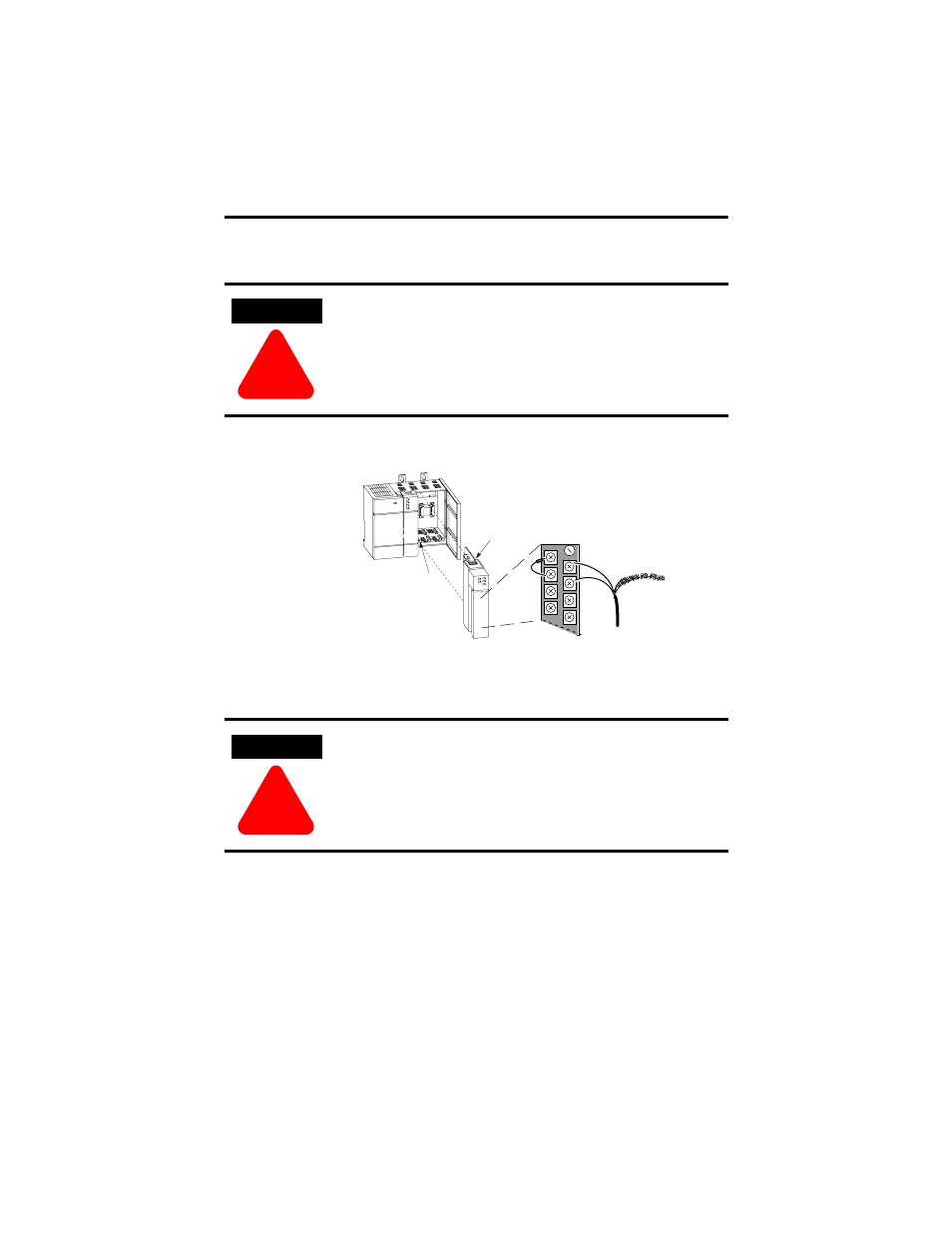
Insert/remove the module into/from the I/O chassis
(slot 1 in this example procedure).
card
guide
module release,
top and bottom
Connect thermocouple wires to channels 0-3.
We show an example for channel 0. Make sure
both cold junction compensation (CJC) devices
are securely attached with correct polarity.
CHL 0±
CJC A
Device
CHL 0+
Thermocouple Wire
Terminal Block
CHL 1+
CHL 1±
Important:
Ground all thermocouple shields
to earth ground at I/O chassis
with 3/8º braid wire. See User
Manual, figure 3.2.
+
±
Important:
Thermocouple inputs are highly
susceptible to electrical noise.
To minimize interference:
Place processor and I/O chassis
in an industrial enclosure.
± Keep signal wires as far from
power and load lines as possible.
Use shielded, twisted-pair
thermocouple extension wire.
Ground each shield only at one end.
Use correct thermocouple polarity.
Keep all unshielded leads short.
Connect the terminal block GND
(#18) to nearest I/O chassis mtg.
bolt with 12 gauge stranded wire.
Install the Module and Connect the Thermocouples
To install your module into the chassis:
1. Turn off the chassis power supply.
WARNING
!
If you insert or remove the module while backplane power is
on, an electrical arc can occur. This could cause an explosion
in hazardous location installations. Be sure that power is
removed or the area is nonhazardous before proceeding.
WARNING
!
If you insert or remove the module while backplane power is
on, an electrical arc can occur. This could cause an explosion
in hazardous location installations. Be sure that power is
removed or the area is nonhazardous before proceeding.