Specifications mounting dimensions – Rockwell Automation 1794-ASBLT/A FLEX I/O Remote I/O Adapter Installation Instructions User Manual
Page 5
5
Publication 1794-IN110A-EN-P - August 2005
Specifications
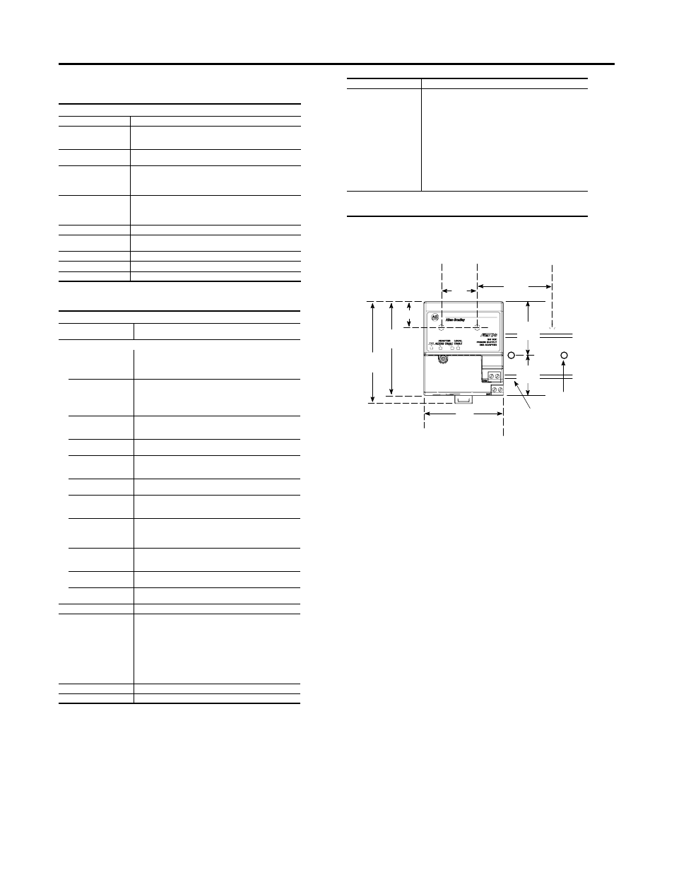
Mounting Dimensions
(
Specifications - Remote I/O Adapter, Cat. No. 1794-ASBLT/D
I/O Capacity
8 modules
Power Supply
Power supply must be capable of providing a turn-on inrush surge
current of 23 A (at 24V dc) for 2 ms for each adapter connected to
the power supply.
Input Voltage Rating
24V dc nominal
19.2V to 31.2 V dc (includes 5% ac ripple)
Communication Rate
57.6 kbps
115.2 kbps
230 kbps
NOTE: PLC5/15 and PLC5/25 can only support 57.6 kbps
Indicators
Power - green
Adapter Active - green
Adapter Fault - red
Local Fault - red
Flexbus Output Current
640 mA maximum
Isolation Voltage
50V continuous
Tested at 850V dc for 1 s between user power and flexbus
Current Draw
330 mA at 24V dc; 450 mA maximum
Power Dissipation
4.6 W maximum @ 31.2V dc
Thermal Dissipation
Maximum 1.7 BTU/hr @ 31.2V dc
General Specifications
Dimensions
3.4H x 2.7W x 2.7D inches
87H x 69W x 69D mm
Environmental Conditions
Operating Temperature
IEC 60068-2-1 (Test Ad, Operating Cold),
IEC 60068-2-2 (Test Bd, Operating Dry Heat),
IEC 60068-2-14 (Test Nb, Operating Thermal Shock):
0 to 55 °C (32 to 131 °F)
Storage Temperature
IEC 60068-2-1 (Test Ab, Unpackaged Nonoperating Cold),
IEC 60068-2-2 (Test Bb, Unpackaged Nonoperating Dry Heat),
IEC 60068-2-14 (Test Na, Unpackaged Nonoperating Thermal
Shock):
–40 to 85 °C (–40 to 185 °F)
Relative Humidity
IEC 60068-2-30 (Test Db, Unpackaged Nonoperating
Damp Heat):
5 to 95% non-condensing
Vibration
IEC60068-2-6 (Test Fc, Operating):
5g @ 10-500 Hz
Shock
IEC60068-2-27 (Test Ea, Unpackaged shock):
Operating 30g
Non-operating 50g
Emissions
CISPR 11:
Group 1, Class A (with appropriate enclosure)
ESD Immunity
IEC 61000-4-2:
4 kV contact discharges
8 kV air discharges
Radiated RF Immunity
IEC 61000-4-3:
10V/m with 1kHz sine-wave 80%AM from 30MHz to 2000MHz
10V/m with 200Hz 50% Pulse 100%AM at 900Mhz
10V/m with 200Hz 50% Pulse 100%AM at 1890Mhz
EFT/B Immunity
IEC 61000-4-4:
±2 kV at 5 kHz on power ports
±2 kV at 5 kHz on communications ports
Surge Transient
Immunity
IEC 61000-4-5:
±2 kV line-earth(CM) on communications ports
Conducted RF Immunity
IEC 61000-4-6:
10Vrms with 1 kHz sine-wave 80%AM from 150 kHz to 80 MHz
Enclosure Type Rating
None (open-style)
Conductors
Wire Size
Category
1
Communications:
12 AWG (2.5mm2) …22 AWG (0.34mm2) solid or stranded copper
wire rated at 75°C or greater, 3/64 inch (1.2mm) insulation
maximum.
Power:
12 AWG (2.5mm2) …22 AWG (0.34mm2) solid or stranded copper
wire rated at 75°C or greater, 3/64 inch (1.2mm) insulation
maximum."
2 on communication ports
3 on power ports
Terminal Screw Torque
7 pound-inches (0.8 Nm)
Remote I/O Cable
Belden 9463 as specified in publication ICCG-2.2
Remote I/O connector Plug
Part Number 942029-03
Certifications (when
product is marked)
2
C
UL
US
UL Listed Industrial Control Equipment, certified for US
and Canada
C
UL
US
UL Listed for Class I, Division 2, Groups A, B, C and D
Hazardous locations, certified for US and Canada
CSA
CSA certified Process Control Equipment
CSA
CSA certified Process Control Equipment for Class I,
Division 2, Groups A, B, C and D Hazardous locations
CE
European Union 89/336/EEC EMC Directive,
compliant with:
EN 61000-6-4; Industrial Emissions
EN 50082-2; Industrial Immunity
EN 61326; Meas./Control/Lab., Industrial Requirements
EN 61000-6-2; Industrial Immunity
C-Tick Australian Radiocommunications Act compliant with
AS/NZS CISPR 11, Industrial Emissions
1
You use this category information for planning conductor routing as described in Allen-Bradley
publication 1770-4.1, Industrial Automation Wiring and Grounding Guidelines.
2
For the latest up-to-date information, see the Product Certification link at www.ab.com for Declarations of
Conformity, Certificates and other certification details.
Inches
(Millimeters)
3.4
(87)
3.2
(80)
2.7
(68)
.83 (21)
1794-ASBLT/D
3.4H x 2.7W x 2.7D
(87H x 68W x 69D)
1.4
(35)
A
2.3
(59)
A
= Mounting hole dimensions for optional wall/panel mounting kit
B
B
= DIN rail
2.0
(50)
1.2
(30)
C
C
= Secure DIN rail approximately every 200mm
1794-ASBLT