Install your adapter module, Component identification, 1794-asblt – Rockwell Automation 1794-ASBLT/A FLEX I/O Remote I/O Adapter Installation Instructions User Manual
Page 2
2
Publication 1794-IN110A-EN-P - August 2005
North American Hazardous Location Approval
Remote I/O Adapter, Cat. No. 1794-ASBLT Series D
These adapters are shipped configured for standard addressing mode. In
Standard Addressing Mode, the 1794-ASBLT series D adapter can be used as a
replacement for 1794-ASB series A and B remote I/O adapters.
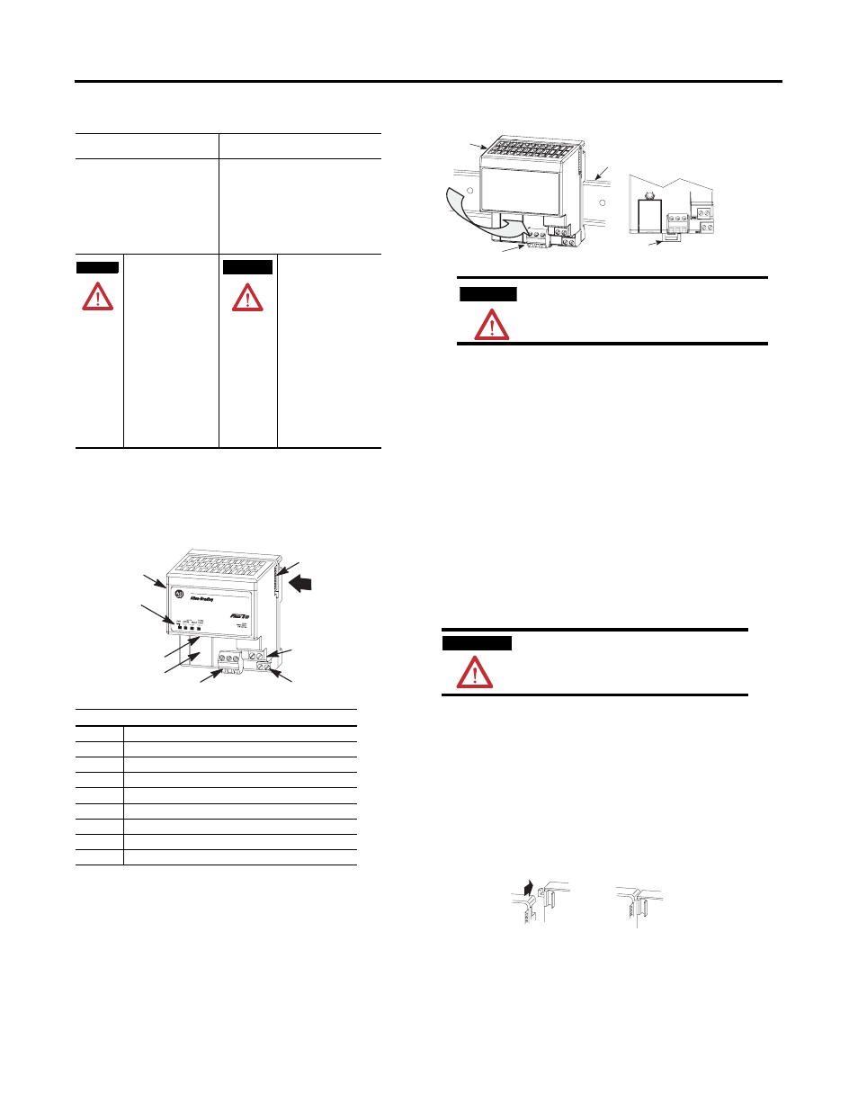
Install Your Adapter Module
Mount on a DIN Rail Before Installing the Terminal Base Units
1. Hook the lip on the rear of the adapter onto the top of the DIN rail,
and rotate the adapter module onto the rail.
2. Press the adapter module down onto the DIN rail until flush. Locking
tab C will snap into position and lock the adapter module to the DIN
rail.
3. If the adapter module does not lock in place, use a screwdriver or
similar device to move the locking tab down while pressing the
adapter module flush onto the DIN rail, and release the locking tab to
lock the adapter module in place. If necessary, push up on the locking
tab to lock.
4. Connect the adapter wiring as shown under “Wiring” later in this
document.
Mount (or Replace) the Adapter on an Existing System
1. Remove the RIO plug-in connector from the front of the adapter.
2. Disconnect any wiring jumpered to the adjacent terminal base.
3. Open the module latching mechanism and remove the module from
the base unit to which the adapter will be attached.
4. Push the flexbus connector toward the right side of the terminal base
to unplug the backplane connection. (When fully retracted, you will
see a raised dot on the connector.)
5. Release the adapter locking tab and remove the adapter module.
6. Before installing the new adapter, notice the notch on the right rear of
the adapter. This notch accepts the hook on the terminal base unit.
The notch is open at the bottom. The hook and adjacent connection
point keep the terminal base and the adapter tight together, reducing
the possibility of a break in communication over the backplane.
7. Complete the adapter mounting as shown below.
The following information applies when
operating this equipment in hazardous
locations:
Informations sur l’utilisation de cet équipement en
environnements dangereux :
Products marked “CL I, DIV 2, GP A, B, C, D” are
suitable for use in Class I Division 2 Groups A, B, C,
D, Hazardous Locations and nonhazardous locations
only. Each product is supplied with markings on the
rating nameplate indicating the hazardous location
temperature code. When combining products within
a system, the most adverse temperature code
(lowest “T” number) may be used to help determine
the overall temperature code of the system.
Combinations of equipment in your system are
subject to investigation by the local Authority
Having Jurisdiction at the time of installation.
Les produits marqués "CL I, DIV 2, GP A, B, C, D" ne
conviennent qu’à une utilisation en environnements de
Classe I Division 2 Groupes A, B, C, D dangereux et non
dangereux. Chaque produit est livré avec des marquages sur
sa plaque d’identification qui indiquent le code de
température pour les environnements dangereux. Lorsque
plusieurs produits sont combinés dans un système, le code
de température le plus défavorable (code de température le
plus faible) peut être utilisé pour déterminer le code de
température global du système. Les combinaisons
d’équipements dans le système sont sujettes à inspection
par les autorités locales qualifiées au moment de
l’installation.
EXPLOSION HAZARD
• Do not disconnect
equipment unless power has
been removed or the area is
known to be nonhazardous.
• Do not disconnect
connections to this equipment
unless power has been
removed or the area is known
to be nonhazardous. Secure
any external connections that
mate to this equipment by
using screws, sliding latches,
threaded connectors, or other
means provided with this
product.
• Substitution of components
may impair suitability for Class
I, Division 2.
• If this product contains
batteries, they must only be
changed in an area known to
be nonhazardous.
RISQUE D’EXPLOSION
• Couper le courant ou s’assurer
que l’environnement est classé
non dangereux avant de
débrancher l'équipement.
• Couper le courant ou s'assurer
que l’environnement est classé
non dangereux avant de
débrancher les connecteurs. Fixer
tous les connecteurs externes
reliés à cet équipement à l'aide de
vis, loquets coulissants,
connecteurs filetés ou autres
moyens fournis avec ce produit.
• La substitution de composants
peut rendre cet équipement
inadapté à une utilisation en
environnement de Classe I,
Division 2.
• S’assurer que l’environnement
est classé non dangereux avant de
changer les piles.
Component Identification
1
Remote I/O Adapter Module
2
Indicators
3
Communication reset button (PRL)
4
Access door to switches S1 and S2
5
Switches S1 and S2 (behind door)
6
Remote I/O cable connector
7
+V dc connections
8
-V common connections
9
Flexbus connector
WARNING
A
VERTISSEMENT
1
2
3
4, 5
6
7
8
9
1794-ASBLT
ATTENTION
During mounting of all devices, be sure that all
debris (such as metal chips or wire strands) is kept
from falling into the module. Debris that falls into
the module could cause damage on power up.
WARNING
If you connect or disconnect wiring while the field-side
power is on, an electrical arc can occur. This could cause
an explosion in hazardous location installations. Be sure
that power is removed or the area is nonhazardous before
proceeding.
A
B
C
C