Rockwell Automation 1794-IM8,1794-OM8 FLEX I/O 220V ac Input and Output Modules Inst. Inst. User Manual
Page 4
Publication 1794-IN104A-EN-P - March 2004
4
PN 957824-75
Supersedes Publication 1794-5.57 - Feb 1999, and 1794-5.58 - Feb 1999
Copyright © 2004 Rockwell Automation, Inc. All rights reserved. Printed in the U.S.A.
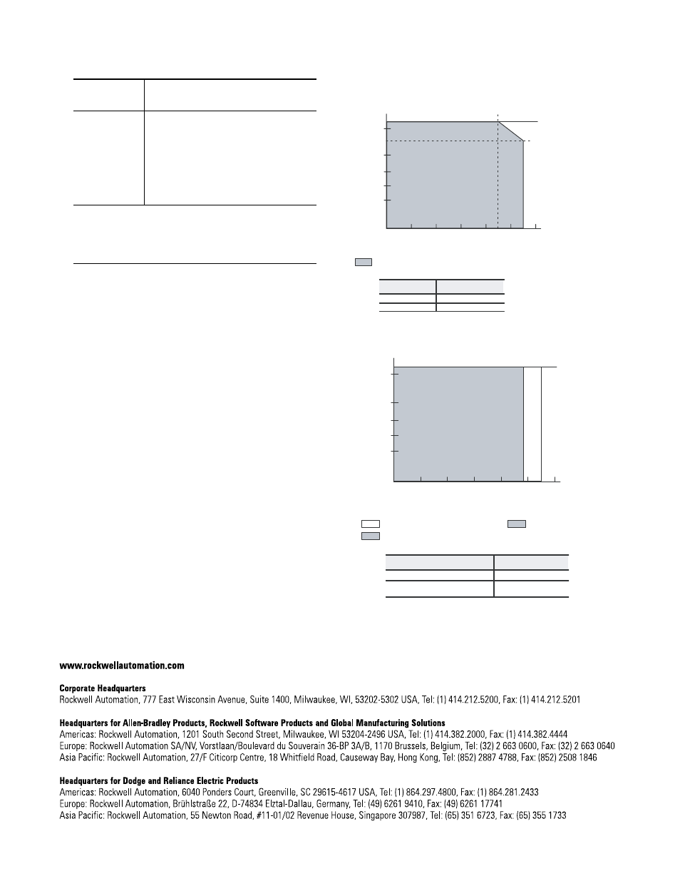
1794-IM8 Derating Curve
1794-OM8 Derating Curve
Conductors
Wire Size
Category
4
12 to 22AWG (4 to 0.25mm
2
) stranded copper wire rated at 60°C or
higher
3/64 inch (1.2mm) insulation maximum
2
Certifications (when
product is marked)
5
UL
UL Listed Industrial Control Equipment
CSA CSA certified for Class I, Division 2, Groups A, B, C and D
Hazardous locations
CE
5
European Union 89/336/EEC EMC Directive,
compliant with:
EN 61000-6-4; Industrial Emissions
EN 50082-2; Industrial Immunity
EN 61326; Meas./Control/Lab., Industrial Requirements
EN 61000-6-2; Industrial Immunity
European Union 73/23/EEC LVD Directive, compliant with:
EN 61131-2; Programmable Controllers
C-Tick
5
- Australian Radiocommunications Act compliant with
AS/NZS CISPR 11, Industrial Emissions
1
Input off-to-on filter time is the time from a valid input signal to recognition by the module. Input on-to-off filter
time is time from the input signal dropping below the valid level to recognition by the module.
2
Delay time is the time from the mreceipt of an output on or off command to the output actually turning on or off.
3
Module outputs are not fused. We recommend that outputs be fused. If not using the 1794-TBNF, and fusing is
desired, it must be provided externally.
4
You use this category information for planning conductor routing as described in Allen-Bradley
publication 1770-4.1, Industrial Automation Wiring and Grounding Guidelines.
5
For the latest up-to-date information, see the Product Certification link at www.ab.com for Declarations of
Conformity, Certificates and other certification details. For notification of any additional release notes, refer to
www.ab.com/manuals/.
0
150
10
20
30
40
50
55
60
V
in
On–state
Voltage
(V ac)
Ambient Temperature
o
C
The area within the curve represents the safe operating range for the module under various
conditions of user supplied 220V ac supply voltages and ambient temperatures.
= All mounting positions (including normal horizontal, vertical,
inverted horizontal) safe operating range
175
190
205
220
250
264
46
235
Voltage (maximum)
Temperature (maximum)
264
46
250
55
0
150
10
20
30
40
50
55
60
V
in
O n–state
Voltage
(V ac)
Ambient Temperature
o
C
The area within the curve represents the safe operating range for the module
under various conditions of user supplied 220V ac supply voltages and ambient
temperatures.
= Other mounting positions (including inverted horizontal, vertical)
safe operating range
175
190
205
220
235
250
264
49
= Normal mounting safe operating range. Includes
Mounting
Temperature (maximum)
normal horizontal
55
Other mounting positions
(including inverted horizontal, vertical)
49