Configuring your ac module – Rockwell Automation 1794-IM8,1794-OM8 FLEX I/O 220V ac Input and Output Modules Inst. Inst. User Manual
Page 2
2
Publication 1794-IN104A-EN-P - March 2004
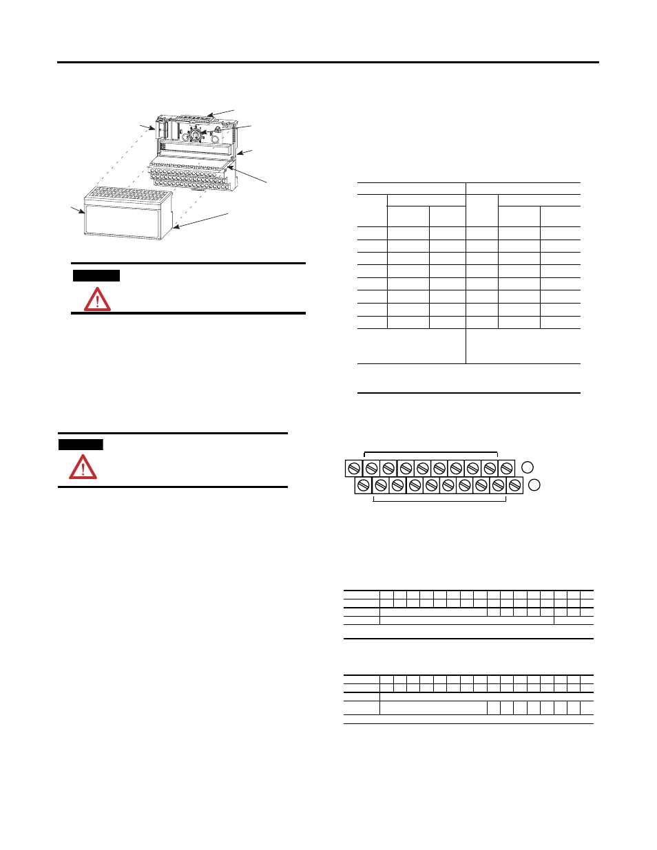
Installing Your 220V ac Digital Input or Output Module
The module mounts on a 1794 terminal base.
1. Rotate the keyswitch (1) on the terminal base (2) clockwise to position
8 as required for this type of module.
2. Make certain the flexbus connector (3) is pushed all the way to the left
to connect with the neighboring
terminal base/adapter. You cannot install the module unless the
connector is fully extended.
3. Make sure the pins on the bottom of the module are straight so they
will align properly with the connector in the terminal base.
4. Position the module (4) with its alignment bar (5) aligned with the
groove (6) on the terminal base.
5. Press firmly and evenly to seat the module in the terminal base unit.
The module is seated when the latching mechanism (7) is locked into
the module.
Connecting Wiring for the 1794-IM8 and -OM8
1. Connect individual input or output wiring to numbered terminals on
row (B) as indicated in the table below.
2. 1794-IM8: Connect the associated 220V ac L1 power lead of the input
device to the corresponding odd numbered terminal (C-1, 3, 5, 7, 9,
11, 13, or 15) on row (C) for each input as indicated in the table below.
(The 220V L1 power terminals of row (C) are internally connected
together.)
1794-OM8: Connect the associated 220V ac common L2 lead of the
output device to the corresponding odd numbered terminal (C-1, 3, 5,
7, 9, 11, 13, or 15) on row (C) as indicated in the table below. (The
220V L2 commons of odd numbered terminals on row (C) are
internally connected together.)
3. Connect 220V ac power (L1) to terminal 34 on the row (C).
4. Connect 220V ac common (L2) to terminal 16 on the
row (B).
5. If daisychaining L1 power to the next terminal base, connect a jumper
from terminal 51 (220V ac L1) on this base unit to terminal 34 on the
next base unit.
6. If continuing 220V ac common (L2) to the next base unit, connect a
jumper from terminal 33 (220V common L2) on this base unit to
terminal 16 on the next base unit.
Wiring Connections for the 1794-IM8 and -OM8
1794-TBN or -TBNF Terminal Base Wiring for 1794-IM8 and
1794-OM8
Configuring Your ac Module
Image Table Memory Map for the 1794-IM8
Image Table Memory Map for the 1794-OM8
ATTENTION
During mounting of all devices, be sure that all debris (metal
chips, wire strands, etc.) is kept from falling into the module.
Debris that falls into the module could cause damage on
power up.
WARNING
If you remove or insert the module while the
backplane power is on, an electrical arc can occur.
This could cause an explosion in hazardous location
installations. Be sure that power is removed or the
area is nonhazardous before proceeding.
1
2
3
4
5
6
7
1794-IM8
1794-OM8
Input
1
1794-TBN
Output
1794-TBN, -TBNF
Input
Terminal
220V ac
Supply
Output
Terminal
Common
Input 0
B-0
C-1
1
Output 0
B-0
C-1
2
Input 1
B-2
C-3
1
Output 1
B-2
C-3
2
Input 2
B-4
C-5
1
Output 2
B-4
C-5
2
Input 3
B-6
C-7
1
Output 3
B-6
C-7
2
Input 4
B-8
C-9
1
Output 4
B-8
C-9
2
Input 5
B-10
C-11
1
Output 5
B-10
C-11
2
Input 6
B-12
C-13
1
Output 6
B-12
C-13
2
Input 7
B-14
C-15
1
Output 7
B-14
C-15
2
B = Even numbered Input terminals 0-14,
ac common terminals 16 and 33
C = Power terminals C-34 and C-51, and
odd numbered input terminals 1 thru 15
B = Even numbered Output terminals 0-14, ac
common terminals 16 and 33
C = Power terminals C-34 and C-51, and odd
numbered terminals 1-15 on row C.
1 C-1, 3, 5, 7, 9, 11, 13 and 15 on the 1794-TBN are internally connected in the module to
220V ac L1.
2 C-1, 3, 5, 7, 9, 11, 13 and 15 on the 1794-TBN are internally connected in the module to
220V ac common L2.
Dec.
15
14
13
12
11
10
9
8
7
6
5
4
3
2
1
0
Oct.
17
16
15
14
13
12
11
10
7
6
5
4
3
2
1
0
Read
Not used - set to 0
I7
I6
I5
I4
I3
I2
I1
I0
Write
Not used - set to 0
Filter Time FT
Where
I = Input status
FT = Input filter time.
Dec.
15
14
13
12
11
10
9
8
7
6
5
4
3
2
1
0
Oct.
17
16
15
14
13
12
11
10
7
6
5
4
3
2
1
0
Read
Not used - set to 0
Write
Not used - set to 0
O
7
O
6
O
5
O
4
O
3
O
2
O
1
O
0
Where
O = Output status
16
0
1
2
3
4
5
6
7
8
9
10
11
12
13
14
15
51
33
34
L1
L2
L1
L2
B
C
Even Numbered I/O Terminals 0 thru 14
Odd Numbered I/O Terminals 1 thru 15
(1794-TBN shown)
L1 = 220V ac power - Connect to terminal C-34
L2 = 220V ac common - Connect to terminal B-16
Use B-33 and C-51 for daisychaining to the next terminal base unit