Single-ended encoder wiring (open collector), Single-ended encoder output waveforms – Rockwell Automation 1746-HSCE2 Multi-Channel High-Speed Counter Installation Instructions User Manual
Page 12
12 Multi-Channel High-Speed Counter
Publication 1746-IN002A-US-P
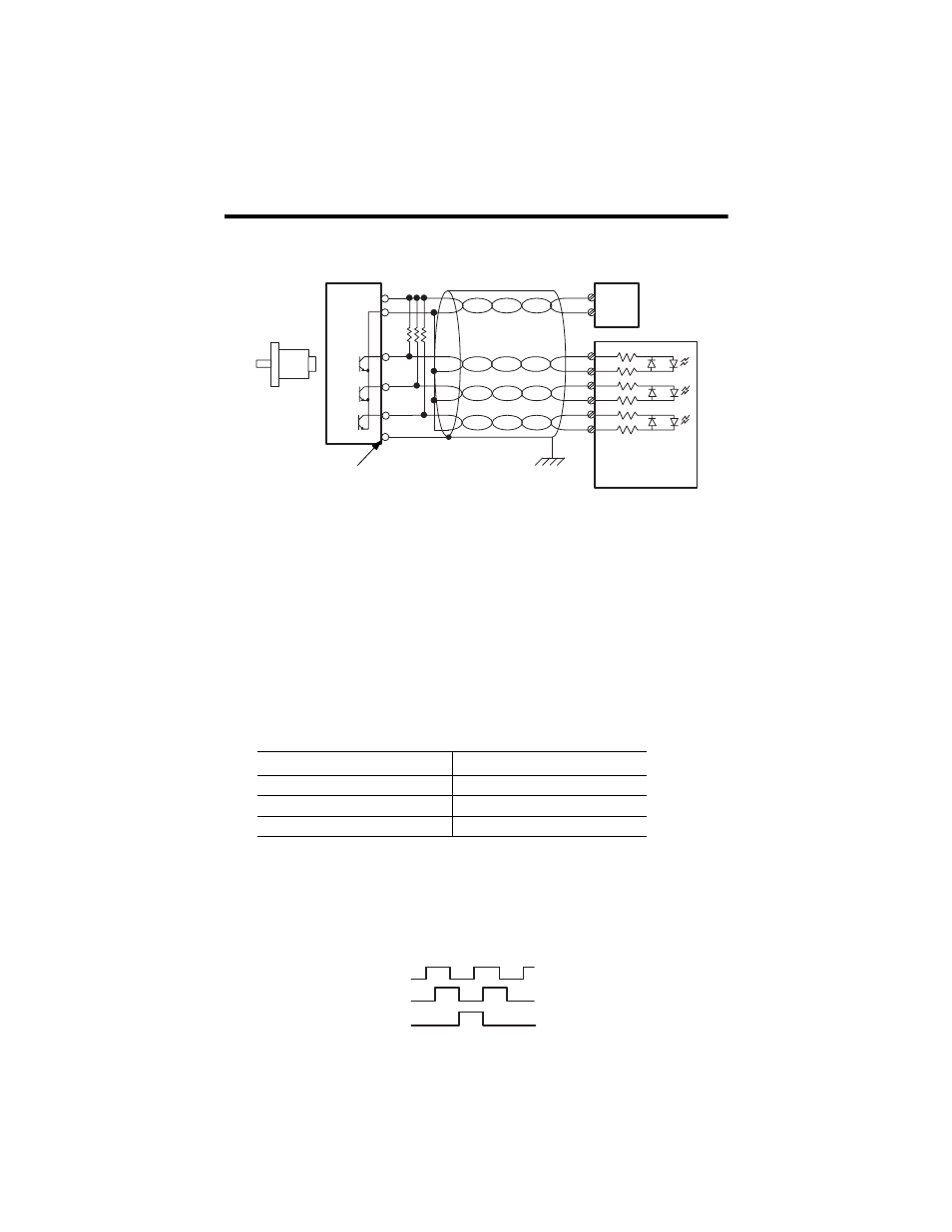
Single-Ended Encoder Wiring (Open Collector)
(1)
Refer to your encoder manual for proper cable type. The type of cable used should be twisted
pair, individually shielded cable with a maximum length of 300m (1000 ft.).
(2)
External resistors are needed if not internal to the encoder. The pull-up resistor (R) value
depends on the power supply value. The table below shows resistor values for typical supply
voltages. To calculate the resistor value, use one of the following formulas:
For 5V dc jumper position:
For 24V dc jumper position:
where:R = pull-up resistor value
Vcc = power supply voltage
Vmin = 4.2 V dc
Imin = 6.3 mA
Single-Ended Encoder Output Waveforms
The figure below shows the single-ended encoder output waveforms. When the
waveform is low, the encoder output transistor is on. When the waveform is high,
the encoder output transistor is off.
Power Supply Voltage (Vcc)
Pull-up Resistor Value (R)
(1)
(1)
Resistance values may change, depending upon your application.
5V dc
127
Ω
12V dc
238
Ω
24V dc
2140
Ω
A
B
Z
A(+)
A(–)
B(+)
B(–)
Z(+)
Z(–)
GND
VS
+VDC
COM
R
(2)
Power
Supply
Allen-Bradley
845H Series
single-ended
encoder
Earth
Module Inputs
cable
(1)
shield
shield/housing
Connect only if housing is electronically
isolated from the motor and ground.
R
Vcc
Vm in
–
(
)
Imin
----------------------------------
=
R
Vcc
Vmin
–
(
)
Imin
----------------------------------
1K
Ω
–
=
A
B
Z