Rockwell Automation 1771-IGD TTL Input Module Installation Instructions User Manual
Page 8
TTL Input Module
8
Publication 1771ĆIN022B-EN-P - September 2002
!
ATTENTION
Remove power from the 1771 I/O chassis
backplane and field wiring arm before removing
or installing an I/O module.
•
Failure to remove power from the backplane or
wiring arm could cause module damage,
degradation of performance, or injury.
•
Failure to remove power from the backplane
could cause injury or equipment damage due to
possible unexpected operation.
Connect wiring to the input module using the field wiring arm (cat.
no. 1771-WH) shipped with the module (shown in the connection
diagram below). Make your connections as follows:
1. Attach the field wiring arm to the pivot bar on the bottom of the
I/O chassis.
2. Pivot the wiring arm upward and push it into the module until the
wiring arm clicks into position. The field wiring arm is designed
to let you install and remove the module without disconnecting
the wires.
!
ATTENTION
Do not apply ac or reverse dc voltage to
module terminals. Circuitry at the input of
module may be damaged.
3. Separate the shielded cables from wiring that radiates electrical
noise. Refer to category 2, low power dc I/O lines, in publication
1770-4.1, ‘‘Programmable Controller Wiring and Grounding
Guidelines”.
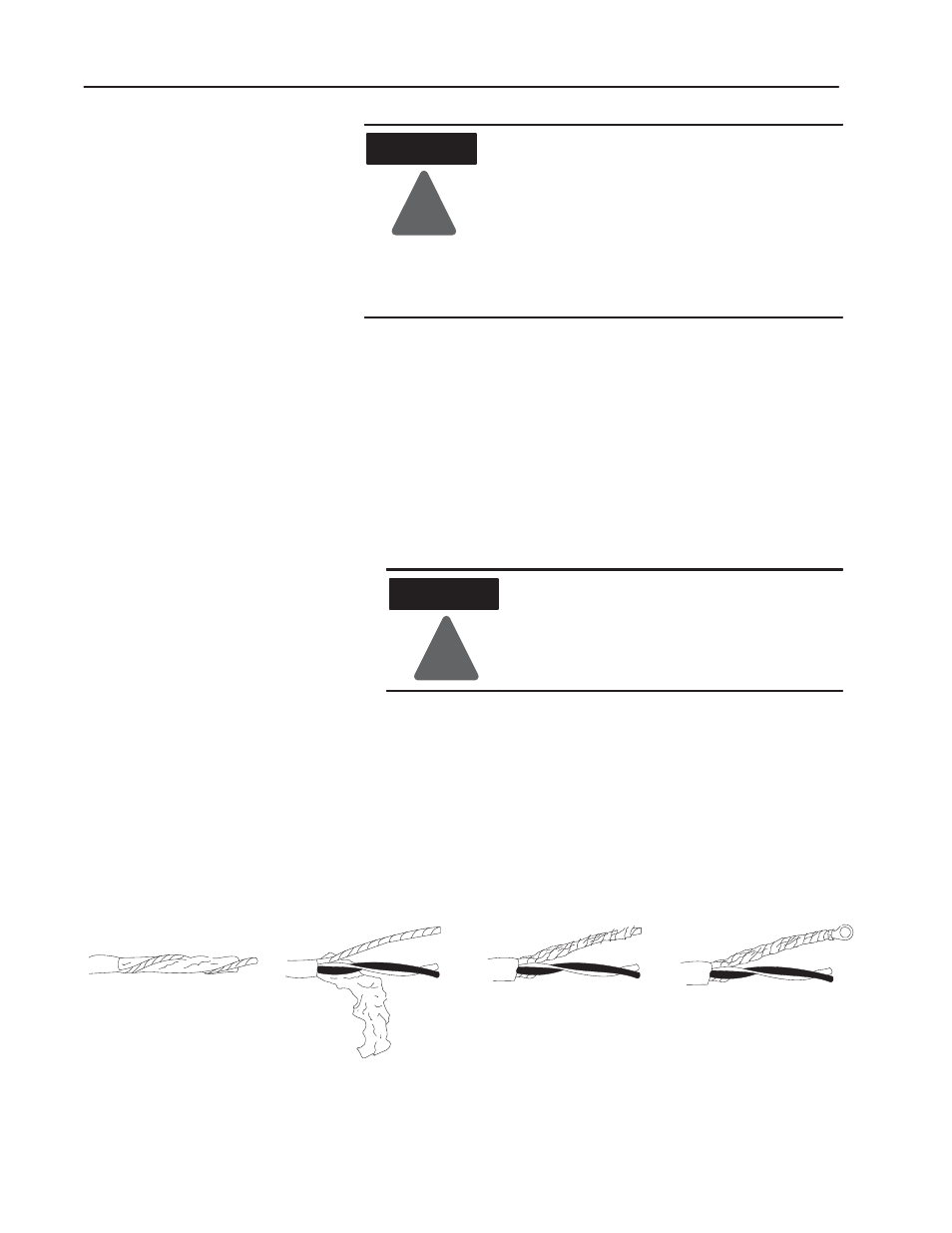
4. Prepare the cable for grounding by doing the following:
Remove a length of cable
jacket from the Belden 8761 cable.
Pull the foil shield and bare
drain wire from the insulated wires.
Bare drain
wire
Insulated
wires
Foil
shield
Twist the foil shield and drain
wire together to form a single strand.
Attach a ground lug.
20104
Belden 8761 Cable
5. Ground the single strand (at the ground lug end) to the grounding
stud on the I/O chassis or by using single-point grounding.
Connect Wiring to the
Input Module