Specifications – Rockwell Automation 1794-AENT FLEX I/O EtherNet/IP Adapter Module Installation Instructi User Manual
Page 6
6 FLEX I/O EtherNet/IP Adapters Installation Instructions
Publication 1794-IN082C-EN-P - October 2007
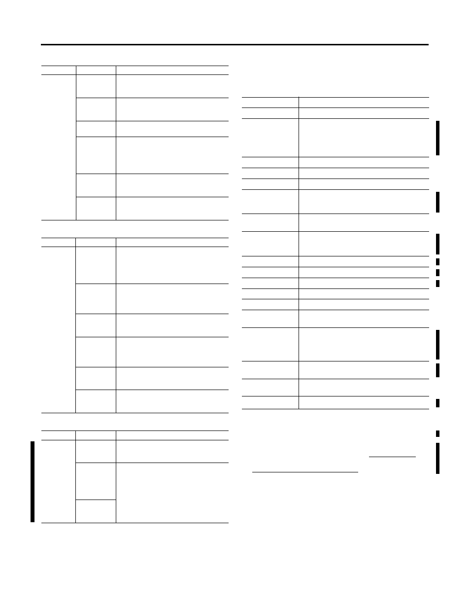
Module Status Indicators
Network Status Indicators
Link Status Indicator
Specifications
FLEX I/O EtherNet/IP Adapter - 1794-AENT
Indicator
Status
Description
Module
Status
Indicator
Off -
No Power
Adapter does not have 24V dc power.
Make sure power is being supplied to the
adapter.
Flashing
Green -
Standby
Adapter not configured.
Configure adapter.
Green -
Operational
Adapter operating correctly.
No action required.
Flashing Red
- Minor Fault
A recoverable fault has been detected.
This could be caused by an incorrect or
inconsistent configuration.
Check configuration and reconfibure as
needed.
Red -
Major Fault
An unrecoverable fault has been detected.
Recycle power to the adapter. If this does
not clear the fault, replace the adapter.
Flashing Red
and Green -
Self Test
Adapter performing power-up self test.
Wait until completed.
Indicator
Status
Description
Network
Status
Indicator
Off -
Not Powered,
No IP
Address
Adapter is not powered, or does not have
an IP address.
• Verify there is power and the adapter
is correctly wired to the power supply.
• Make sure the adapter is configured.
Flashing
Green -
No
Connections.
Adapter has obtained an IP address, but
has no established connections.
Green -
CIP
Connections
Adapter has an IP address and at least one
established connection.
Flashing Red
-
Connection
Timeout
One or more of the connections in which
the adapter is the target has timed out.
Red -
Duplicate IP
Address
Adapter has detected that its IP address is
already in use. Configure the adapter with
a unique IP address.
Flashing Red
and Green -
Self Test
Adapter performing power-up self test.
Indicator
Status
Description
Link Status
Indicator
Off -
No link
exists.
Verify network cabling. Correct as
necessary.
Flashing
Green -
I/O is being
transmitted
or received.
Normal operation. No action required.
Steady Green
- A link
exists.
Attribute
Value
I/O capacity
8 modules
Power supply
To comply with the CE Low Voltage Directive (LVD),
this equipment must be powered from a source
compliant with the following:
Safety Extra Low Voltage (SELV) or Protected Extra
Low Voltage (PELV).
Input voltage rating
24V dc nom
Input voltage range
19.2…31.2V dc (includes 5% ac ripple)
Communication rate
10/100 Mbps
Indicators
Module Status - red/grn
Network Status - red/grn
Link Status - grn
Flexbus output
current
640 mA max
Isolation voltage
50V continuous, Basic Insulation Type
Tested at 1000V ac for 60 s, power to Flexbus to
EtherNet
Power consumption
550 mA max, 440 mA max at 24V dc
Power dissipation
7.3 W max @ 19.2V dc
Thermal dissipation
24.9 BTU/hr @ 19.2V dc
Ethernet connector
RJ45 Cat. 5
Enclosure type rating None (open-style)
North American
temp code
T4A
Power conductors
Wire size
0.34…2.5 mm
2
(22…12 AWG) stranded copper
wire rated at 75 °C (167 °F) or higher, 1.2 mm (3/64
in.) insulation max
Category
(1)
(1)
You use this category information for planning conductor routing as described in
Allen-Bradley Industrial Automation Wiring and Grounding Guidelines,
publication 1770-4.1.
1 - on power ports
2 - on communications ports
Terminal screw
torque
0.8 Nm (7 lb-in)
Publications
(2)
(2)
For additional installation information, refer to ODVA EtherNet/IP Media
Planning and Installation manual, publication 148 document number 42604 in Rockwell Automation Knowledgebase at
User Manual ENET-UM001