Interpret the status indicators – Rockwell Automation 1790D-XXXX DeviceNet Digital Base Terminal Block CompactBlock LDX I/O Series B User Manual
Page 15
DeviceNet Digital Base Terminal Block CompactBlock LDX I/O 15
Publication
1790-IN012B-EN-P - July 2008
•
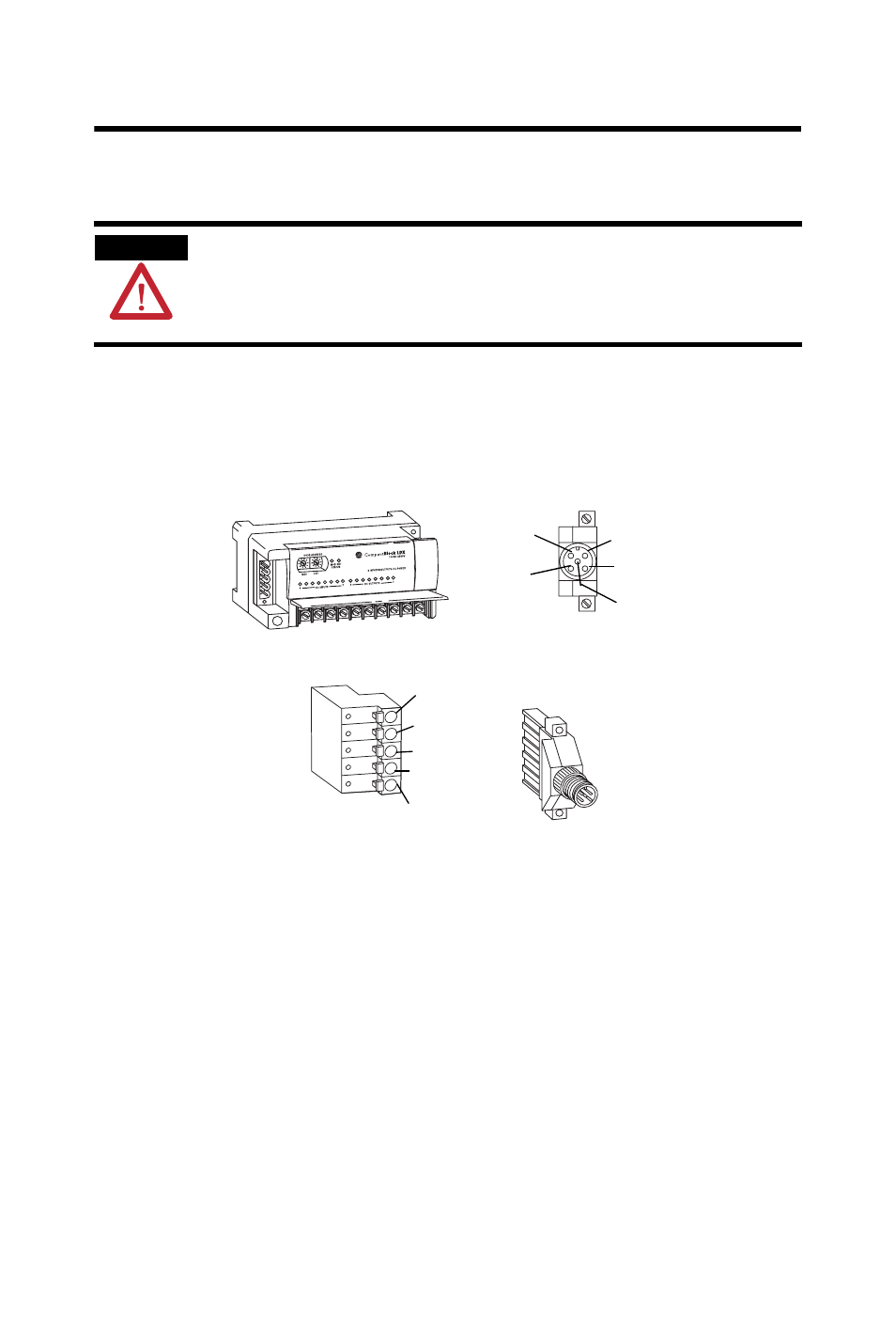
1799-DNC5MMS - 5-position open-style to 12 mm (0.47 in.)
connector with locking screws
1. Connect the DeviceNet wiring (drop line) to one of the
DeviceNet connectors as shown in the figure, noting that a
color-coded wiring diagram is printed next to the connector
on the left side of the base block.
2. Attach the connector to the base block once you have
properly wired the drop line to the connector.
3. Use the locking screws on the connector to fasten it to the
base block, if applicable.
Interpret the Status Indicators
Read this section for information about how to interpret base block
status indicators. The base block has these status indicators:
•
Block status
•
Network status
WARNING
If you connect or disconnect the communication cable with power applied to
this module or any device on the network, an electrical arc can occur. This
could cause an explosion in hazardous location installations.
Be sure that power is removed or the area is nonhazardous before proceeding.
Wiring Diagram for
1799-DNETCON
Connector
Wiring Diagram for
1799-DNC5MMS
Connector
V+ Red
V- Black
Drain/Shield
Can_H White
Can_L Blue
V+ Red
Can_H White
Drain/Shield
Can_L Blue
V- Black
44164