Specifications – Rockwell Automation 1794-VHSC Very High Speed Counter Module Installation Instruction User Manual
Page 5
5
Publication 1794-IN067C-EN-P - January 2012
Specifications
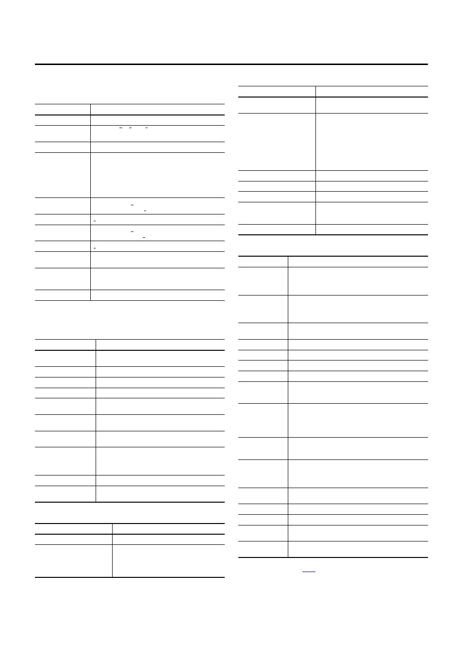
Input Specifications
Attribute
Value
Number of input channels
2
Number of inputs per
counter
2 groups of A/A, B/B, and Z/Z pairs with 5V DC or
15…24V DC terminations
Input voltage
5V DC or 15…24V DC (Determined by terminal base terminations)
Input current
5V DC terminations:
19.1 mA @ 5V DC
25.7 mA @ 6V DC
15…24V DC terminations:
6.1 mA @ 15V DC
10.2 mA @ 24V DC
Voltage, input, off-state
5V DC terminations: <1.25V DC
15…24V DC terminations: <1.8V DC
Current, input, off-state
<0.25 mA
Voltage, input, on-state
5V DC terminations: >2.6V DC
15…24V DC terminations: >12.5V DC
Current, input, on-state
>5 mA
Voltage, on-state, max
5V DC terminations: ±6V
15…24V DC terminations (Refer to Derating Curve)
Input frequency, max
1.0 MHz counter and encoder X1 (no filters)
500 kHz encoder X2 (no filters)
250 kHz endocer X4 (no filters)
Input filter selections
Off, 10
μs, 100μs, 1.0ms, 10.0ms per A/B/Z group
Output Specifications
Attribute
Value
Number of outputs
2 isolated groups of 2:
(0.5A @ 5V DC, max; 1.0A @ 12…24V DC, max)
Output control
Outputs can be tied to 8 compare windows
Voltage range, output supply
5…7V DC; 10…31V DC
Leakage current, off-state
Less than 300
μA
Voltage drop, on-state
5V DC terminations: 0.9V DC @ 0.5 A
12…24V DC terminations: 0.9V DC @ 1.0 A
Current, on-state, max
5V DC terminations: 0.5 A
12…24V DC terminations: 1.0 A
Current per
output pair, max
5V DC terminations: 0.5 A
12…24V DC terminations: 1.0 A
Short circuit current
5V DC terminations: 0.9A
12…24V DC terminations: 4.0A
Outputs are short-circuit protected and turned off until power is
cycled.
Surge current
2A for 50 ms, repeatable every 2 s
Delay TimeOff to On
On to Off
25
μs (load dependent)
150
μs (load dependent)
General Specifications
Attribute
Value
Module location
1794-TB3G and 1794-TB3GS
External DC power supply voltage
Voltage range, nom
Supply voltage
Supply current
24V DC
19.2…31.2V DC (includes 5% AC ripple)
100 mA @ 24V DC
Dimensions, HxWxD (with module
installed on terminal base)
94 x 94 x 69 mm
(3.7 x 3.7 x 2.7 in.)
Isolation voltage
50V (continuous), Basic Insulation Type, between six
isolated areas including:
Flexbus
Module 24V DC power
A0/B0/Z0 inputs
A1/B1/Z1 inputs
00/01 and output power supply 1
02/03 and output power supply 2
Tested @ 850V DC for 1 s
FlexBus current
75 mA @ 5V DC (with terminal base power off)
Power dissipation, max
5.0 W @ 31.2V DC
Thermal dissipation, max
17.1 BTU/hr @ 31.2V DC
Indicators (field side driven, logic side
indication)
1 green/red power/status indicator
6 yellow input status indicators – logic side
4 yellow output tatus indicators – logic side
Keyswitch position
1
Environmental Specifications
Attribute
Value
Temperature, operating
IEC 60068-2-1 (Test Ad, Operating Cold),
IEC 60068-2-2 (Test Bd, Operating Dry Heat),
IEC 60068-2-14 (Test Nb, Operating Thermal Shock):
0…55 °C (32…131 °F)
Temperature,
nonoperating
IEC 60068-2-1 (Test Ab, Un-packaged Non-operating Cold),
IEC 60068-2-2 (Test Bb, Un-packaged Non-operating Dry Heat),
IEC 60068-2-14 (Test Na, Un-packaged Non-operating Thermal Shock):
-40…85 °C (-40…185 °F)
Relative humidity
IEC 60068-2-30 (Test Db, Unpackaged Damp Heat):
5…95% non-condensing
Vibration
IEC60068-2-6 (Test Fc, Operating): 5g @ 10…500 Hz
Shock, operating
IEC60068-2-27 (Test Ea, Unpackaged shock): 30 g
Shock, nonoperating
EC60068-2-27 (Test Ea, Unpackaged shock): 50 g
Emissions
CISPR 11: Group 1, Class A (with appropriate enclosure)
ESD Immunity
IEC 61000-4-2:
6 kV contact discharges
8 kV air discharges
Radiated RF immunity
IEC 61000-4-3:
10V/m with 1 kHz sine-wave 80% AM from 80…2000 MHz
10V/m with 200 Hz 50% Pulse 100% AM at 900 MHz
10V/m with 200 Hz 50% Pulse 100% AM at 1890 MHz
10V/m with 1 kHz sine-wave 80% AM from 2000…2700 MHz
EFT/B immunity
IEC 61000-4-4:
±2 kV @ 5 kHz on power ports
±2 kV @ 5 kHz on signal ports
Surge transient
immunity
IEC 61000-4-5:
±1 kV line-line(DM) and ±2 kV line-earth(CM) on power ports
±1 kV line-line(DM) and ±2 kV line-earth(CM) on signal ports
±2 kV line-earth(CM) on shielded ports
Conducted RF immunity
IEC 61000-4-6:
10V rms with 1 kHz sine-wave 80%AM from 150 kHz…80 MHz
Enclosure type rating
None (open-style)
Wire size
Determined by installed terminal base
Wiring category
(1)
2 – on signal ports
2 – on power ports
Terminal base screw
torque
Determined by installed terminal base
(1)
Use this Conductor Category information for planning conductor routing. Refer to Industrial Automation Wiring and
Grounding Guidelines, publication
.
General Specifications
Attribute
Value