Wiring connections using 1794-tb3g and 1794-tb3gs, Wiring connections, Input map – Rockwell Automation 1794-VHSC Very High Speed Counter Module Installation Instruction User Manual
Page 2
2
Publication 1794-IN067C-EN-P - January 2012
2. Make certain the FlexBus connector (1) is pushed all the way to the left to
connect with the neighboring terminal base/adapter. You cannot install
the module unless the connector is fully extended.
3. Make sure the pins on the bottom of the module are straight so they will
align properly with the connector in the terminal base.
4. Position the module (7) with its alignment bar (6) aligned with the groove
(5) on the terminal base.
5. Press firmly and evenly to seat the module in the terminal base unit. The
module is seated when the latching mechanism (2) is locked into the
module.
Connecting Wiring for the 1794-TB3G, and 1794-TB3GS
Wiring Connections Using 1794-TB3G and 1794-TB3GS
ATTENTION
To reduce susceptibility to noise, power analog modules and
digital modules from separate power supplies. Do not exceed a
length of 3 m (9.8 ft) for DC power cabling.
ATTENTION
Do not daisychain power or ground from this terminal base unit
to any AC or DC digital module terminal base units.
ATTENTION
Do not wire more than two conductors on any single terminal.
Wiring Connections
Encoder
Inputs
Channel 0
Channel 1
24V
Inputs
5V
Inputs
24V Inputs
5V Inputs
A
A-0
B-17
A-8
B-25
A
A-1
B-18
A-9
B-26
B
A-2
B-19
A-10
B-27
B
A-3
B-20
A-11
B-28
Z
A-4
B-21
A-12
B-29
Z
A-5
B-22
A-13
B-30
Outputs
Source Out
Return
O0
A-6
B-23
O1
A-7
B-24
O2
A-14
B-31
O3
A-15
B-32
24V DC
Terminals C-34 and C-50
24V COM
Terminals C-35 and C-51
5 or 24V output power
Terminals C-37 and C-46
-V output power
Terminals C-39 and C-48
Chassis Ground
Terminals B-16, B-33, C-38, C-40…C-45, C-47
ATTENTION
Do not connect 24V signals to the +5V input terminals.
Permanent damage to the module will result.
Input Map
Dec.
15
14
13
12
11
10
9
8
7
6
5
4
3
2
1
0
Oct.
17
16
15
14
13
12
11
10
7
6
5
4
3
2
1
0
0
Channel 0 Current Count (least significant word)
1
Channel 0 Current Count (most significant word)
2
Channel 1 Current Count (least significant word)
3
Channel 1 Current Count (most significant word)
4
Channel 0 Stored/Accumulated Count (least significant word)
5
Channel 0 Stored/Accumulated Count (most significant word)
6
Channel 1 Stored/Accumulated Count (least significant word)
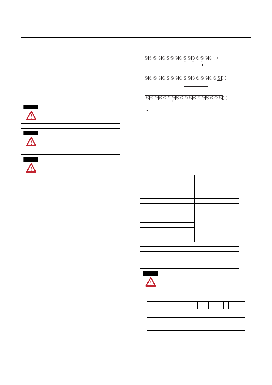
17 18 19 20 21 22 23 24 25 26 27 28 29 30 31 32 33
0 1 2 3 4 5 6 7 8 9 10 11 12 13 14 15
16
35 36 37 38 39 40 41 42 43 44 45 46 47 48 49 50 51
34
Chassis
Gnd
Chassis
Gnd
+24V DC COM
COM
Chassis Grounds for Shields
A
B
C
A
A
B
Z
B
Z O0 O1
O2 O3
A
A
B
Z
B
Z
A
A
B
Z
B
Z
A
A
B
Z
B
Z
R0
R1
R2
R3
+V
-V
+V
-V
24V Inputs
5V Inputs
5V Inputs
24V Inputs
A, A = incremental encoder input A (+5 or +24V DC)
B, B = incremental encoder input B (+5 or +24V DC)
Z, Z = incremental encoder input Z (+5 or +24V DC)
O = sourcing outputs
R = returns for sourcing outputs
+V = +5 or +24V DC isolated power externally supplied for outputs (1A max)
+24V DC= 24V DC terminal base power for module
-V = negative isolated power connection (1A max)
COM = return for 24V DC terminal base power for module
Chassis Gnd = chassis ground for input or output cable shields
Input power for Output O0 (A-6); Output O1 (A-7) - C-37 (+) and C-39 (-)
Input power for Output O2 (A-14); Output O3 (A-14) - C-46 (+) and C-48 (-)
NC = No Connection
+24V DC
NC
NC
Chas
GND
Chas
GND