Rockwell Automation 1794-IE4XOE2,1794-IE8,1794-OE4,D17946.5.2 FLEX I/O ANALOG MODULE User Manual
Page 43
4–11
Configuring Your Module and Reading Status from Your Module with a Remote I/O Adapter
Publication 1794Ć6.5.2 - May 1996
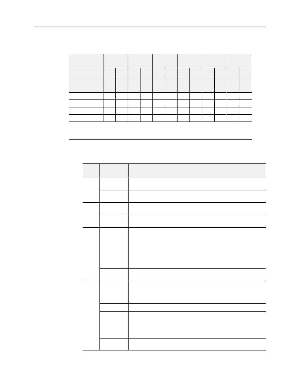
Range Selection Bits for the 1794-IE4XOE2/B Analog Combo
Module
Channel No.
Input
Channel 0
Input
Channel 1
Input
Channel 2
Input
Channel 3
Output
Channel 0
Output
Channel 1
F0
C0
F1
C1
F2
C2
F3
C3
F4
C4
F5
C5
Decimal Bits
(Octal Bits)
00
08
(10)
01
09
(11)
02
10
(12)
03
11
(13)
04
12
(14)
05
13
(15)
4-20mA
0
1
0
1
0
1
0
1
0
1
0
1
0-10V dc/0-20mA
1
0
1
0
1
0
1
0
1
0
1
0
Ć10 to +10V dc
1
1
1
1
1
1
1
1
1
1
1
1
Off
1
0
0
0
0
0
0
0
0
0
0
0
0
C = Configure select bit
F = Full range bit
1
When configured to off, individual channels will return or send either 0V or 0mA on Series B modules. On Series modules, 2V or 4mA is output
until the module is configured.
Word/Bit Descriptions for the 1794-IE4XOE2/B Analog Combo
Module Write
Word
Decimal Bit
(Octal Bit)
Definition
Write
Bits 00-14
(00-16)
Channel 0 analog data - 12Ćbit left justified two's complement number; unused
lower bits are zero; 4Ć20mA uses all 16 bits.
Write
Word 0
Bits 15
(17)
Channel 0 analog data sign bit.
Word 1
Bits 00-14
(00-16)
Channel 1 analog data - 12Ćbit left justified two's complement number; unused
lower bits are zero; 4Ć20mA uses all 16 bits.
Word 1
Bits 15
(17)
Channel 1 analog data sign bit.
Word 2
Bits 00-01
Multiplex control bits (M) for individual channels. These bits control the safe state
analog outputs - Bit 00 corresponds to output channel 0, and bit 01 corresponds to
output channel 1.
1 = use words 0 and 1 (analog value) as directed by channel number n
0 = use words 6 and 7 (safe state analog value) as directed by channel number n
When bits 00Ć01 are all cleared (0) simultaneously by a communication error or user
choice thru the programmable controller program, word 3 full range and configure
select bits are preserved at their last setting.
Bits 02-15
(02-17)
Not used - set to 0.
Bits 00-05
Full range bits (F) for individual channels - Bit 00 corresponds to input channel 0,
bit 01 corresponds to input channel 1, bit 02 corresponds to input channel 3, bit 03
corresponds to input channel 3, bit 04 corresponds to output channel 1, and bit 05
corresponds to output channel 2. Refer to Range Bit Selections.
Bits 06Ć07
Not used - set to 0.
Word 3
Bits 08-13
(10Ć15)
Configure select bits (C) for individual channels - Bit 08 corresponds to input
channel 0, bit 09 (11) corresponds to input channel 1, bit 10 (12) corresponds to
input channel 2, bit 11 (13) corresponds to input channel 3, bit 12 (14) corresponds
to output channel 0, and bit 13 (15) corresponds to output channel 1. Refer to Range
Bit Selections.
Bits 14Ć15
(16Ć17)
Not used - set to 0.