Bonding and grounding the chassis – Rockwell Automation 1770 Industrial Automation Wiring and Grounding Guidelines User Manual
Page 6
Industrial Automation Wiring and Grounding Guidelines
6
Publication 1770-4.1 – February 1998
Make good electrical connection between each chassis, back-panel,
and enclosure through each mounting bolt or stud. Wherever contact
is made, remove paint or other non-conductive finish from around
studs or tapped holes.
Bonding and Grounding the Chassis
With solid-state controls, proper bonding and grounding helps
reduce the effects of emi and ground noise. Also, since bonding and
grounding are important for safety in electrical installations, local
codes and ordinances dictate which bonding and grounding methods
are permissible.
For example, for U.S. installations, the National Electrical Code
(NEC) gives you the requirements for safe bonding and grounding,
such as information about the size and types of conductors and
methods of safely grounding electrical components.
Equipment-Grounding Conductor — In addition to making good
connections through each bolt or stud, use either 1-inch copper braid
or 8 AWG minimum stranded copper wire to connect each chassis,
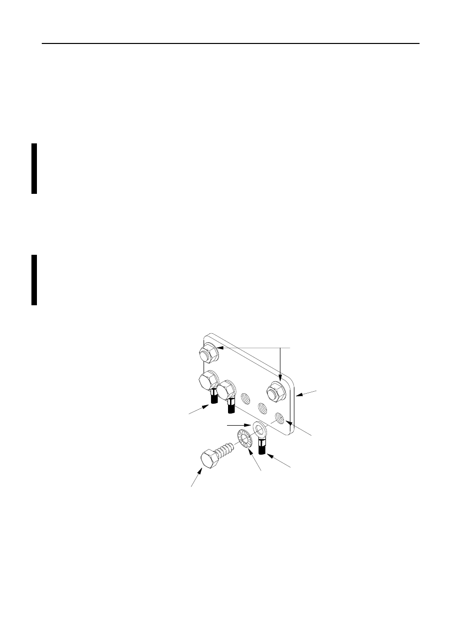
enclosure and central ground bus mounted on the back-panel. Figure
3 shows ground-bus connection details.
Figure 3
Ground Bus Connection Details
Equipment-
13271
grounding
Conductors
Ground
Lug
Bolt
Star
Washer
Ground Bus
Mounting
Ground Bus
Tapped Hole
Grounding-electrode conductor
to grounding-electrode system.
Figure 4 shows enclosure-wall ground connection details. Use a
steel enclosure to guard against emi. If the enclosure door has a
viewing window, it should be a laminated screen or a conductive
optical substrate to block emi. Do not rely on the hinge for electrical
contact between the door and the enclosure; install a bonding wire.