Install the module and field wiring arm – Rockwell Automation 1771-IBN DC (10-30V) INPUT Module Installation Instructions User Manual
Page 8
8 DC (10...30V) Input Module
Publication 1771-IN028D-EN-P - October 2008
Install the Module and Field Wiring Arm
The 1771–IBN module is a modular component of the 1771 I/O system requiring a properly
installed system chassis. Refer to Universal I/O Chassis Installation Instructions publication
for detailed information on acceptable chassis and proper installation and
grounding requirements. Limit the adjacent slot-power dissipation to 10 W maximum.
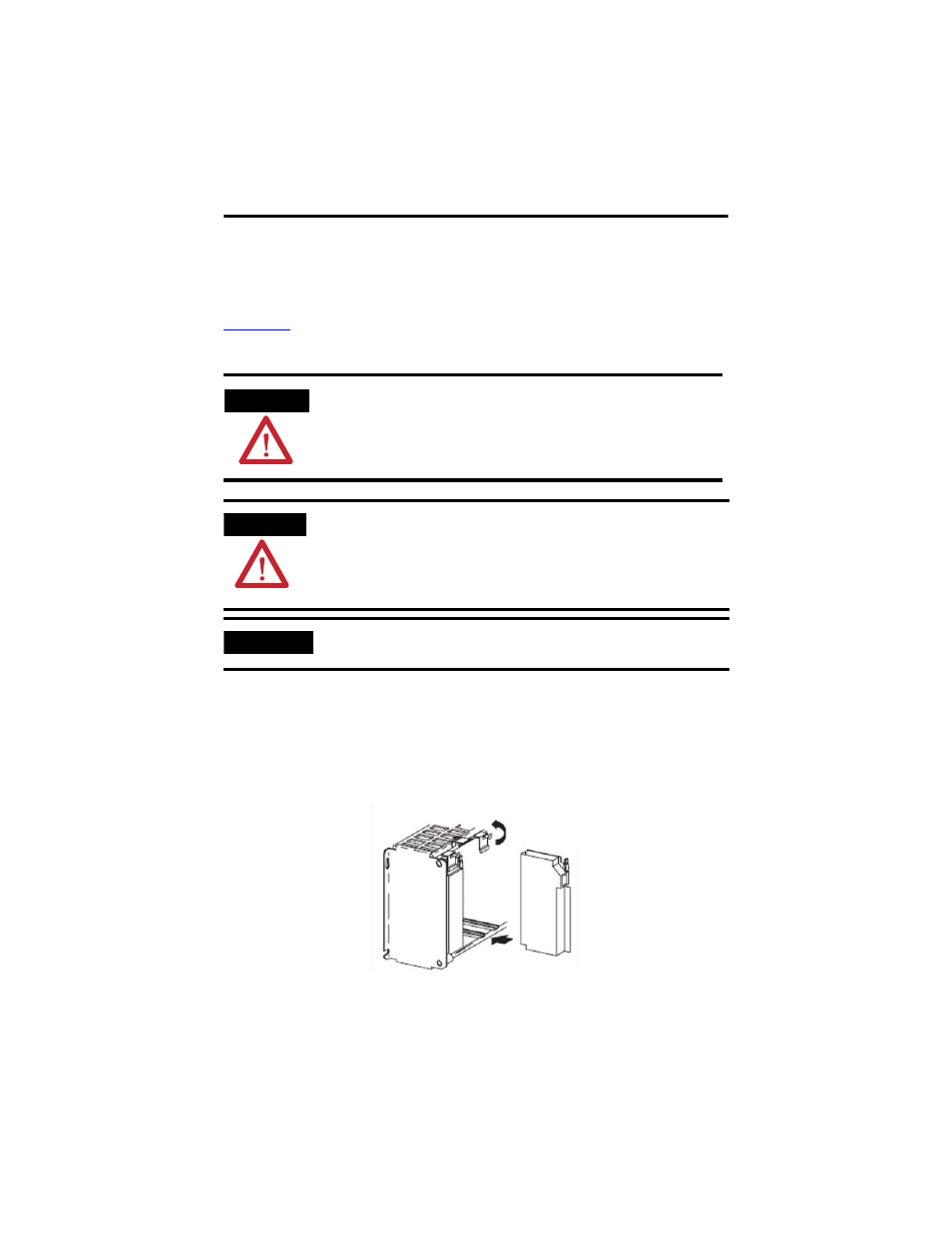
To install the module and field wiring arm, follow this procedure.
1. Place the module in the card guides on the top and bottom of the chassis that guide
the module into position, noting the following:
• For a 1771-A1B, 1771-A2B, 1771-A3B, and 1771-A4B I/O chassis, snap the
chassis latch over the top of the module to secure it.
WARNING
If you insert or remove the module with power applied, or connect or disconnect
the field wiring arm with field-side power applied, an electrical arc can occur. This
could cause an explosion in hazardous location installations. Be sure that power is
removed or the area is nonhazardous before proceeding.
ATTENTION
Remove power from the 1771 I/O chassis backplane before you install the module.
Failure to remove power from the backplane could cause:
• module damage.
• degradation of performance.
• injury or equipment damage due to possible unexpected operation.
IMPORTANT
Apply firm and even pressure on the module to seat it into its backplane connector.