Data table – 1794-ie8xoe4 – Rockwell Automation 1794-IE8XOE4 FLEX I/O DC Input, Output, and Input/Output Analog Modules Installation User Manual
Page 14
14 FLEX I/O DC Input, Output, and Input/Output Analog Modules
Publication 1794-IN106D-EN-E - January 2014
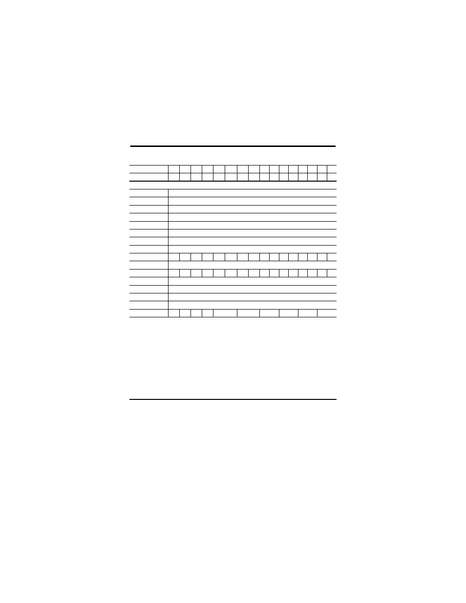
Data Table – 1794-IE8XOE4
Dec.
15
14
13
12
11
10
9
8
7
6
5
4
3
2
1
0
Oct.
17
16
15
14
13
12
11
10
7
6
5
4
3
2
1
0
Read Words
0 - Input 0
Signed 2’s Complement data Value of Channel 0
1 - Input 1
Signed 2’s Complement data Value of Channel 1
2 - Input 2
Signed 2’s Complement data Value of Channel 2
3 - Input 3
Signed 2’s Complement data Value of Channel 3
4 - Input 4
Signed 2’s Complement data Value of Channel 4
5 - Input 5
Signed 2’s Complement data Value of Channel 5
6 - Input 6
Signed 2’s Complement data Value of Channel 6
7 - Input 7
Signed 2’s Complement data Value of Channel 7
8 - Status
PU
FP
GF
NU W3 W2 W1 W0 R7 R6 R5 R4 R3 R2 R1 R0
Write Words
0 - Reserved
EN S1
S0
WR 0
0
0
0
0
0
0
0
0
0
0
0
1 - Output 0
Signed 2’s Complement data Value of Channel 0
2 - Output 1
Signed 2’s Complement data Value of Channel 1
3 - Output 2
Signed 2’s Complement data Value of Channel 2
4 - Output 3
Signed 2’s Complement data Value of Channel 3
5 - Configuration QS 0
0
0
CAB
C89
C67
C45
C23
C01
Where:
PU = Power up bit
FP = Field power fault
GF = General fault
NU = Not used
Wx = Wire off (x = associated channel)
Rx = Out of range (x = associated channel)
EN = Enable outputs
S1/S0 = Safe state source – When EN = 0, these bits indicate source of safe state output.
WR = Wire-off reset
QS = Quick step bit – allows input filter to be reduced during rapid signal changes.
Cxx = Channel Configuration (xx = associated channel pair)