Interpret the led status indicators – Rockwell Automation 1756-DH485 ControlLogix DH-485 Communication Module User Manual User Manual
Page 98
Publication 1756-UM532A-EN-P - May 2006
B-2 Troubleshoot the 1756-DH485 Module
If the alphanumeric indicator on the 1756-DH485 module does not cycle
through these messages when you apply power, refer to the following table and
to the troubleshooting section that follows.
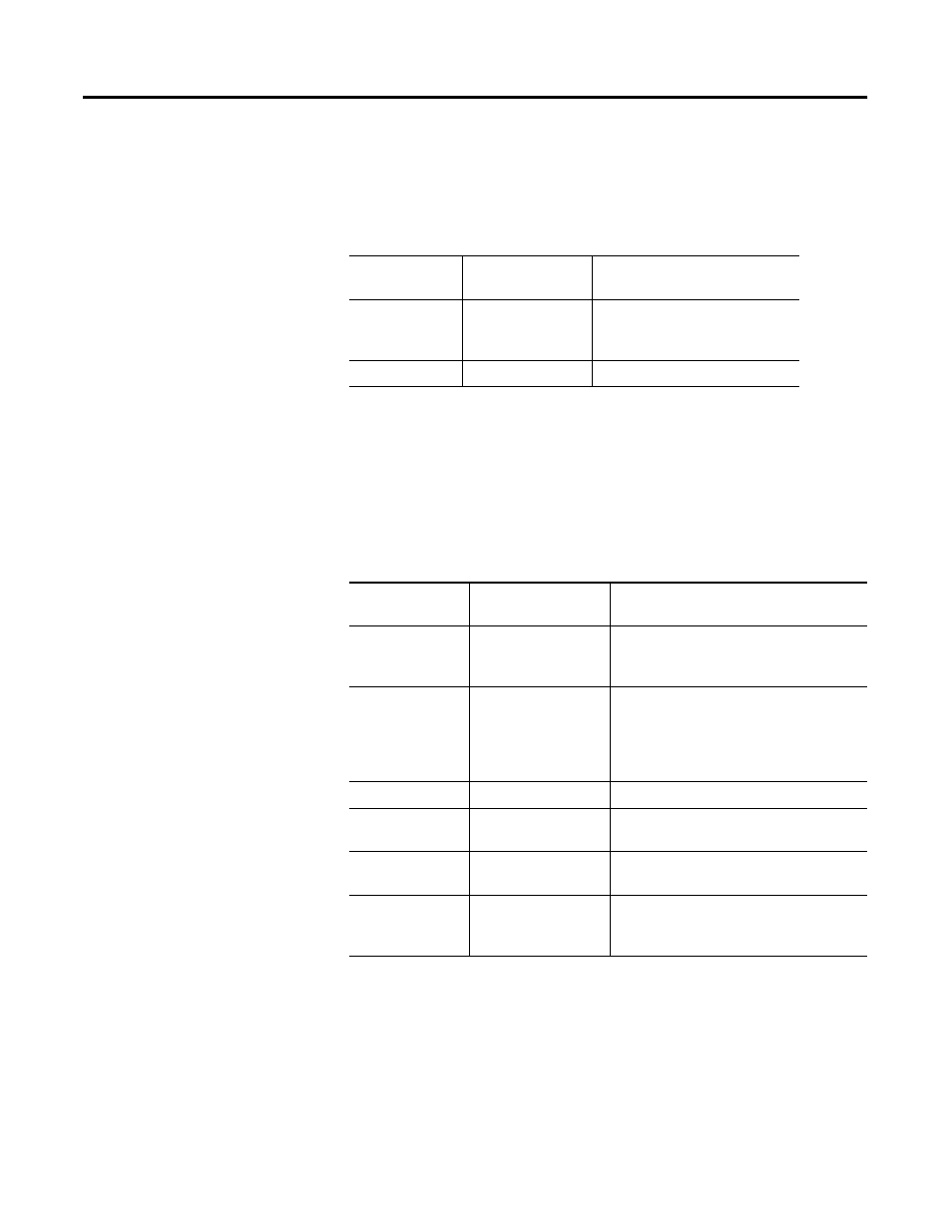
Power Cycle Indicators
Interpret the LED Status
Indicators
The LED status indicators on the module provide information about your
module and the status of each channel. The following tables outline the
indicator condition and the corresponding status, and explain what each
condition means.
Interpret the LED Status Indicators
If the POWER
Indicator is
Power Supply
Status is
Recommended Action
Off
Not operating.
Turn power ON.
Check power wiring connections.
Check fuse.
On
Operating.
None, normal operation.
Module OK
Indicator
Module Status
Recommended Action
Off
Not operating.
Apply chassis power.
Verify module is completely inserted into
chassis and backplane.
Green flashing
Operating but not
routing messages.
None, if no messages are actively being
routed through the module.
To route messages, configure module with
RSLinx software.
Solid Red, then Off Performing self-test.
None, normal operation.
Solid Green
Operating and routing
messages.
Verify module configuration.
Solid Red
In major fault.
Reboot module. If red reoccurs, then
replace module.
Red flashing
In major fault or
configuration fault.
Check alphanumeric indicator and take
action described in the Alphanumeric
Display Descriptions table.