Replacing a fuse – Rockwell Automation 1771-OD16 AC (120V) ISO Output Installation Instructions User Manual
Page 10
AC (120V) Isolated Output Module, 16 Outputs
10
Publication 1771Ć5.21 -February 1997
Each module output is individually fused. You can easily access the
module fuses through the access holes on the side cover. Follow the
procedure below.
!
ATTENTION: Remove power from the 1771 I/O
chassis backplane and wiring arm before removing or
installing an I/O module.
•
Failure to remove power from the backplane could
cause injury or equipment damage due to possible
unexpected operation.
•
Failure to remove power from the backplane or wir-
ing arm could cause module damage, degradation of
performance, or injury.
If a blown fuse occurs:
1. Turn off power to the I/O chassis backplane.
2. Pivot the wiring arm away from the module and pull the module
from the I/O chassis.
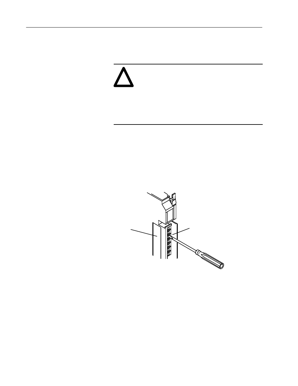
3. Use a small common screwdriver to reach through the front of the
module and carefully pry one end of the fuse out of its holder.
18532
Reach through hole in side cover
and twist and pull to remove fuse.
Pry up on one end of the fuse
to remove it from the holder.
1.
2.
4. Reach through the access hole on the side of the module and
carefully twist and pull to remove the blown fuse. Replace it with
a 3A 2AG slo-blow fuse (Littelfuse part number 229003).
5. Reinstall the module in the I/O chassis.
6. Reposition the wiring arm.
7. Restart system power.
Replacing a Fuse