Specifications, Mounting dimensions, Back cover – Rockwell Automation 1794-ACN15_ACNR15 ControlNet Adapter Module Installation Instructions User Manual
Page 4: Specifications mounting dimensions
Publication 1794-IN101B-EN-P - June 2004
4
PN 957899-40
Supersedes Publication 1794-IN101A-EN-P - August 2003
Copyright © 2004 Rockwell Automation, Inc. All rights reserved. Printed in the U.S.A.
Specifications
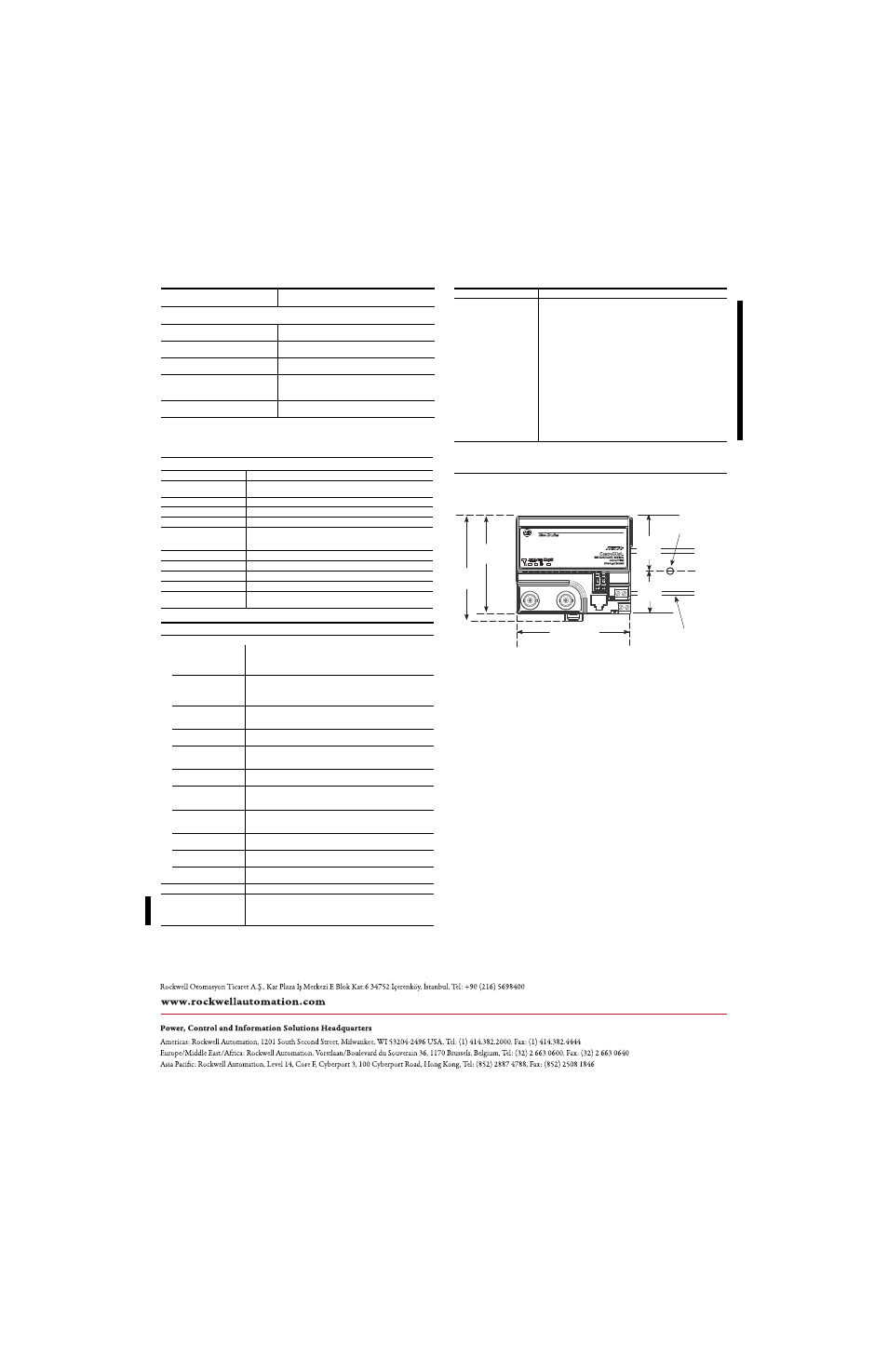
Mounting Dimensions
Status Indicator
Off
No power
Flashing Green
On-line but not connected
Green
On-line, link okay, connected
Flashing Red
I/O module removed, wrong I/O module
inserted, FLASH program update in progress
Red
Critical - adapter failure
Specifications - Cat. No. 1794-ACN15 and -ACNR15
I/O Capacity
8 modules
Input Voltage Rating
24V dc nominal
19.2V to 31.2 V dc (includes 5% ac ripple)
Current Draw
450mA maximum; 330mA @ 24V dc
Inrush Current
23A for 2ms
Communication Rate
5M bps
Indicators
I/O Status - red/green
Comm A - red/green
Comm B - red/green
Flexbus Output Current
640mA maximum
Isolation Voltage
Tested at 850V dc for 1s between user power and flexbus
Power Dissipation
4.6W maximum @ 19.2V dc
Terminal Screw Torque
7 pound-inches (0.8Nm)
Dimensions
3.4H x 3.7W x 2.7D inches
87H x 94W x 69D mm
General Specifications
Environmental Conditions
Operating Temperature
IEC 60068-2-1 (Test Ad, Operating Cold),
IEC 60068-2-2 (Test Bd, Operating Dry Heat),
IEC 60068-2-14 (Test Nb, Operating Thermal Shock):
0 to 55°C (32 to 131°F)
Storage Temperature
IEC 60068-2-1 (Test Ab, Un-packaged Non-operating Cold),
IEC 60068-2-2 (Test Bb, Un-packaged Non-operating Dry Heat),
IEC 60068-2-14 (Test Na, Un-packaged Non-operating Thermal Shock):
–40 to 85°C (–40 to 185°F)
Relative Humidity
IEC 60068-2-30 (Test Db, Un-packaged Non-operating
Damp Heat):
5 to 95% non-condensing
Vibration
IEC60068-2-6 (Test Fc, Operating):
5g @ 10-500Hz
Shock
IEC60068-2-27 (Test Ea, Unpackaged shock):
Operating 30g
Non-operating 50g
Emissions
CISPR 11:
Group 1, Class A (with appropriate enclosure)
ESD Immunity
IEC 61000-4-2:
4kV contact discharges
8kV air discharges
Radiated RF Immunity
IEC 61000-4-3:
10V/m with 1kHz sine-wave 80%AM from 30MHz to 1000MHz
10V/m with 200 50% Pulse 100% AM at 900MHz
EFT/B Immunity
IEC 61000-4-4:
±2kV at 5kHz on communication ports
Surge Transient Immunity
IEC 61000-4-5:
±2kV line-earth(CM) on shielded ports
Conducted RF Immunity
IEC 61000-4-6:
10Vrms with 1kHz sine-wave 80%AM from 150kHz to 30MHz
Enclosure Type Rating
None (open-style)
Conductors
Wire Size
Category
1
22-12AWG (0.34mm
2
-2.5mm
2
) stranded copper wire rated at 75°C or
higher
3/64 inch (1.2mm) insulation maximum
2
LED Indications
Probable Cause
ControlNet Cable
Belden RG-6/U
Certifications (when product is
marked)
2
C
UL
US
UL Listed Industrial Control Equipment, certified for US
and Canada
UL
UL Listed for Class I, Division 2 Group A,B,C,D Hazardous
Locations
C
UL
UL Listed for Class I, Division 2 Group A,B,C,D Hazardous
Locations, certified for Canada
CSA CSA certified Process Control Equipment
CSA CSA certified for Class I, Division 2, Groups A, B, C and D
Hazardous locations
EEx
2
European Union 94/9/EEC ATEX Directive, compliant with:
EN 50021; Potentially Explosive Atmospheres,
Protection “n” ( Zone 2)
CE
2
European Union 89/336/EEC EMC Directive,
compliant with:
EN 61000-6-4; Industrial Emissions
EN 50082-2; Industrial Immunity
EN 61326; Meas./Control/Lab., Industrial Requirements
EN 61000-6-2; Industrial Immunity
C-Tick
2
Australian Radiocommunications Act compliant with
AS/NZS CISPR 11, Industrial Emissions
1
You use this category information for planning conductor routing as described in Allen-Bradley
publication 1770-4.1, Industrial Automation Wiring and Grounding Guidelines.
2
For the latest up-to-date information, see the Product Certification link at www.ab.com for Declarations of
Conformity, Certificates and other certification details. For notification of any additional release notes, refer to
www.ab.com/manuals/.
3.4
(87)
3.2
(80)
3.7
(94)
2.0
(50)
1.2
(30)
A
B
1794-ACN15, -ACNR15
3.4H x 3.7W x 2.7D
(87H x 94W x 69D)
(1794-ACNR15
A = DIN rail
B = Secure DIN rail about every 200mm
shown)