Connecting wiring, Indicators – Rockwell Automation 1794-ACN15_ACNR15 ControlNet Adapter Module Installation Instructions User Manual
Page 3
3
Publication 1794-IN101B-EN-P - June 2004
3. Open the module latching mechanism and remove the module from
the base unit to which the adapter will be attached.
4. Push the flexbus connector toward the right side of the terminal base
to unplug the backplane connection.
5. Release the locking tab and remove the adapter module.
6. Before installing the new adapter, notice the notch on the right rear of
the adapter. This notch accepts the hook on the terminal base unit.
The notch is open at the bottom. The hook and adjacent connection
point keep the terminal base and the adapter tight together, reducing
the possibility of a break in communication over the backplane.
7. Complete the adapter mounting as shown below.
8. Reinstall the module in the adjacent terminal base unit.
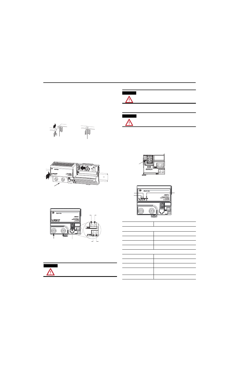
Connecting Wiring
1. Connect the ControlNet network cable to connector, terminal A.
2. 1794-ACNR15 only - Connect the redundant ControlNet network
cable to connector B.
3. Connect +V dc power to the left side of the lower connector, terminal
D.
4. Connect -V common to the left side of the upper connector, terminal
C.
5. Connections E and F are used to pass +V dc power (F) and -V
common (E) to the next module in the series (if required).
6. Set the network address using the 2-button thumbwheel switch G.
Valid settings range from 01 to 99. Press either the + or - buttons to
change the number.
Indicators
WARNING
If you connect or disconnect the ControlNet cable with power
applied to this module or any device on the network, an electrical arc
can ocur. This could cause an explosion in hazardous installations.
Be sure that power is removed or the area is nonhazardous before
proceeding.
30133
C
Push down and in at the same time to lock the adapter to the DIN rail.
When the adapter is locked onto the DIN rail, gently push the flexbus connector into
the adapter to complete the backplane
If the adapter does not lock in place, use a screwdriver or similar device to move the
locking tab down while pressing the adapter flush onto the DIN rail, and release the
locking tab to lock the adapter module in place. If necessary, push up on the locking
tab to lock.
A
C
D
E
F
G
B
ATTENTION
When connecting wiring, torque terminal screws C, D, E and F to 7
pound-inches (0.8Nm).
ATTENTION
Power wiring must be less than 9.8 ft. (3 meters) in length.
LED Indications
Probable Cause
Comm A and Comm B Simultaneously
Off
No power, or reset
Red
Adapter inoperative
Red/Green - flashing alternately
Adapter self-test
Red/Off - flashing alternately
Bad node configuration (duplicate address)
Comm A or Comm B (individually)
Off
Channel disabled
Green
Channel operational
Flashing Green/Off
Temporary network errors
Flashing Red/Off
Cable fault, broken cable, redundancy
warning
Flashing Red/Green
Bad network configuration
Network
Address
Switches
Comm B
Comm A
Status