Configure the module – Rockwell Automation 1771-IL Installation Instructions User Manual
Page 8
Isolated Analog Input Module
8
Publication 1771Ć5.62 - November 1998
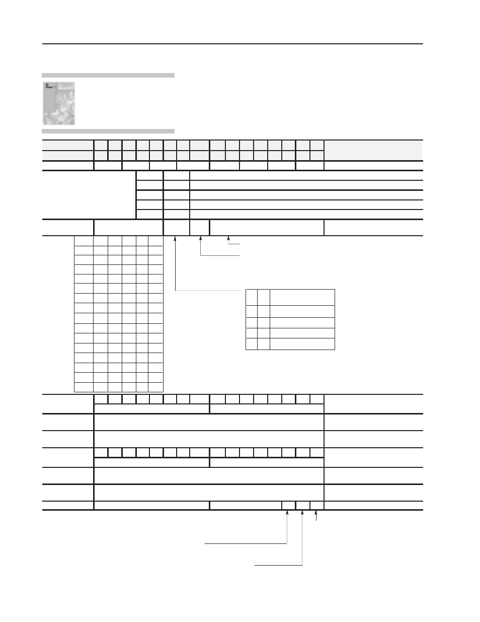
Configure the module to conform to the application that you have
chosen. Use the configuration information below to configure your
module to your specifications.
Dec. Bits
15 14 13 12 11 10 09
08
07 06 05 04 03 02 01 00
Description
Octal Bits
17 16 15 14 13 12 11
10
07 06 05 04 03 02 01 00
Description
Word 1
8
7
6
5
4
3
2
1
Range Selection Ć Channels 1 - 8
Input range selections allow the
Bit 01
Bit 00
Voltage or Current Input
p
g
user to configure the inputs for any of
7 input voltage or current ranges Two
0
0
1 to 5V DC, 4 to 20mA (default)
7 input voltage or current ranges. Two
bits are required for each channel.
0
1
0 to 5V DC, 0 to 20mA
bits are required for each channel.
Bits 00 and 01 for channel 1, bits 02
d 03 f
h
l 2 t
1
0
Ć5 to +5V DC, Ć20 to +20mA
and 03 for channel 2, etc.
1
1
Ć10 to +10V DC, 0 to 10V DC
2
Real Time Sampling
Data
Format
BTW
Format
Digital Filter
Real time sampling, data format, BTW
format, and digital filter
1.0s
900ms
800ms
700ms
600ms
500ms
400ms
300ms
200ms
No RTS
3.1s
100ms
1.5s
2.0s
2.5s
3.0s
0
0
0
0
0
0
0
0
1
0
0
0
0
1
0
0
0
0
1
1
0
0
1
0
0
0
0
1
0
1
0
0
1
1
0
0
0
1
1
1
0
1
0
0
0
0
1
0
0
1
0
1
0
1
0
0
1
1
1
1
1
0
1
0
0
1
1
0
0
1
1
1
1
1
0
1
1
1
1
1
Digital filter reduces effect of noise on input. (Default is no filter.)
BTW format, determines format for scaling, digital filter
constant, and high and low alarms.
Bit 08 (10) = 0 Ć values must be entered in BCD (default)
Bit 08 (10) = 1 Ć values must be entered in Two's Complement Binary
Data format - set to match
your processor.
BCD (default)
Not Used
Two's complement binary
Signed magnitude binary
Bit
10
Bit
09
0
0
0
1
1
0
1
1
3
8
7
6
5
4
3
2
1
8
7
6
5
4
3
2
1
Sign bits, minimum, and maximum
3
Sign bits, maximum negative scaling values
Sign bits, minimum negative scaling values
g
negative scaling values
4, 6, 8, 10, 12, 14,
16, 18
Minimum scaling values for each channel (word 4 to channel 1, word 6 to channel 2, etc.).
Enter in BCD format.
Channels 1 - 8 minimum scaling
5, 7, 9, 11, 13, 15,
17, 19
Maximum scaling values for each channel (word 5 to channel 1, word 7 to channel 2, etc.).
Enter in BCD format.
Channels 1 - 8 maximum scaling
20
8
7
6
5
4
3
2
1
8
7
6
5
4
3
2
1
Sign bits low and high alarm values
20
Sign bits, high alarm values
Sign bits, low alarm values
Sign bits, low and high alarm values
21, 23, 25, 27, 29,
31, 33, 35
Low alarm values for each channel (word 21 to channel 1, word 23 to channel 2, etc.).
Enter in BCD format.
Channels 1 - 8 low alarm
22, 24, 26, 28, 30,
32, 34, 36
High alarm values for each channel (word 22 to channel 1, word 24 to channel 2, etc.).
Enter in BCD format.
Channels 1 - 8 high alarm
37
Inhibit bits for calibration
Not Used
S
G
O
Calibration bits
Offset Calibration Bit - (O) When this bit is
set, offset calibration is to be performed. When
set, no other calibration functions can be set.
Default = 0, no calibration.
Gain Calibration Bit - (G) When this bit is set, gain calibration is to be performed. When
set, no other calibration functions can be performed. Default = 0, no gain calibration.
Save Calibration Values - (S) When this bit is set, new calibration
values will be saved in EEPROM. Default = 0, values not saved.
Inhibit Channel Calibration Bits - (8-15) When this bit is set, that particular
channel will not be calibrated. Bit 8 to channel 1, bit 9 to channel 2, etc.
Default = 0, all channels to be calibrated.
For detailed configuration
information, see chapter 5 of your
Isolated Analog Input Module User
Manual (publication
1771Ć6.5.128).
Configure the Module