Setting the configuration jumpers, Key the backplane connector – Rockwell Automation 1771-IL Installation Instructions User Manual
Page 4
Isolated Analog Input Module
4
Publication 1771Ć5.62 - November 1998
The module has configuration jumpers for determining the input type
(voltage or current) for each input. The module is shipped with the
configuration jumpers positioned for voltage mode. You can
select either voltage or current for each input.
Key the Backplane
Connector
Place your module in any slot in the chassis
except the leftmost slot which is reserved for
processors or adapters.
ATTENTION: Observe the
following precautions when
inserting or removing keys:
•
insert or remove keys with
your fingers
•
make sure that key placement
is correct
Incorrect keying or the use of a
tool can result in damage to the
backplane connector and possible
system faults.
!
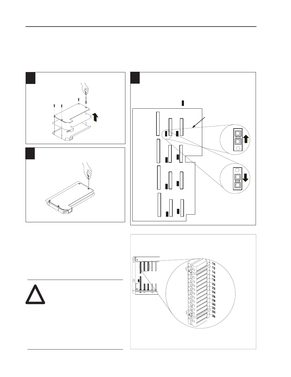
Position thekeying bands in thebackplaneconnectors to correspond to
thekey slots on themodule.
Placethekeying bands:
between 10 and 12
between 32 and 34
You can changetheposition of thesebands if
subsequent system design and rewiring makes
insertion of a different type of module necessary.
Upper
Connector
11022ĆI
I/O chassis
Setting the Configuration
Jumpers
Remove the four screws securing the side cover to
themoduleand removethecovers.
19805
1
Reposition the configuration jumpers associated with each input
channel according to your requirements.
2
The module is shipped with each channel set for voltage mode. If
current mode is desired, you must set a jumper for each channel on
themodulecircuit board. You can mix voltagemodeand current
modesettings.
= Configuration Jumper
Voltage
Mode
Current
Mode
Enlarged View of
Configuration Jumpers
Ch 2
Ch 4
Ch 6
Ch 8
Ch 1
Ch 3
Ch 5
Ch 7
Reposition the cover and secure with the four
screws removed in step 1.
19813
3