Enhanced plc-5 programmable controller overview – Rockwell Automation 1785-l11B, -L20B, -L30B, -L40B, -L40L, -L60B, -L60L, -L80B Enhanced PLC-5 Programmable Controllers Installation Instructions User Manual
Page 6
Publication 1785-IN062A-EN-P - May 2005
6 Enhanced PLC-5 Programmable Controllers
Enhanced PLC-5
Programmable Controller
Overview
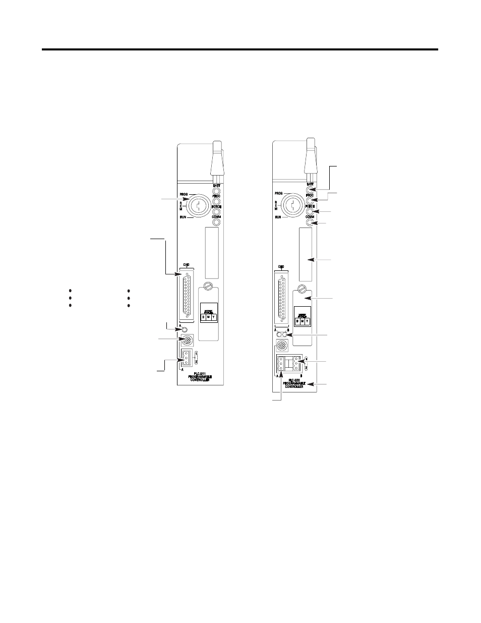
The following illustrations indicate the controller’s front panel components.
PLC-5/11, -5/20, and -5/26 Controller Front Panel
channel 1A communication port;
this 3-pin port is a dedicated DH+ port
battery indicator (red when
the battery is low)
processor RUN/FAULT
indicator (green when
running; red when faulted)
force indicator (amber when
I/O forces are enabled)
channel 0 communication
status indicator (green when
the channel is communicating)
PLC-5 family member designation
Install memory module here
Install battery here
channel 1B communication port;
its default configuration is remote
I/O scanner
channel 1B status indicator
(lights green and red)
keyswitch; selects controller mode
channel 1A communication port; for
the PLC-5/11 controller, the default
configuration is DH+
8-pin mini-DIN, DH+ programming
terminal connection parallel to
channel 1A
channel 1A status indicator
(lights green and red)
Use this port with ASCII or DF1
full-duplex, half-duplex master, and
half-duplex slave protocols. The port's
default configuration supports controller
programming:
channel 0-25-pin D-shell serial port;
supports standard EIA RS-232C and
RS-423 and is RS-422A compatible
one stop-bit
BCC error check
no handshaking
DF1 point-to-point
2400 bps
no parity