Interpreting the status indicators, Troubleshooting, Interpreting the status indicators troubleshooting – Rockwell Automation 1771-ICD DC(20-60V)Input Module Installation Instructions User Manual
Page 6
6
DC (20-60V) Input Module Cat. No. 1771-ICD Series B
Publication 1771-5.29 – February 2000
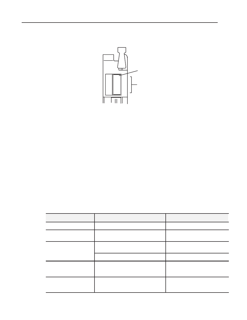
The front panel of your module contains one green, module active
indicator, and 16 red status indicators.
Module Active Indicator (green)
00 to 17 Status Indicators (red)
ACTIVE
00
01
02
03
04
05
06
07
10
11
12
13
14
15
16
17
11935-I
The 1771-ICD/B performs diagnostics in a handshaking mode when
first powered up. Upon successful completion of the diagnostics, the
green module active indicator lights. It turns off if a fault occurs in
the data paths or the opto-isolators.
If a module fault occurs, the module resets its inputs or sets them to
last state, depending on the fault mode selection. The module active
indicator must be on to properly interpret the red status indicators.
The red status indicators are provided for system logic side
indication of individual inputs. When a red indicator lights, voltage
is present on the terminal. The module transfers this information to
the backplane for the processor to read. See ”Troubleshooting” for a
description, probable causes, and recommended actions to take for
common faults based on indicator responses.
Use this table to help you interpret the 1771-ICD/B status indicators
and to troubleshoot module and system faults.
Indicator Status (color)
Description of Fault or System Status
Action to Take
Module active ON (green)
Normal Indication
None
Module active ON (green) and
Input status ON (red)
Check for voltage on terminal
If none, replace module
Module active ON (green) and
Input status OFF
Input devices not functioning properly or faulty
input circuitry on module
1. Check input devices
2. If input devices are OK, replace module
No voltage on terminal
None
Module active OFF
Module is not powered or fault in opto-isolators
and/or data paths; module resets inputs or goes to
last state
1. Check chassis power supply and module
input power
2. If power supplies are OK, replace module
Module active OFF and
Input status ON (red) or OFF
Not valid unless module active indicator is on;
when active is off, indicators do not represent
processor status
1. Check chassis power supply and module
input power
2. If power supplies are OK, replace module
Interpreting the Status
Indicators
Troubleshooting