Wire connections for the 1794-tb3gt – Rockwell Automation 1794-TB3GT Flex I/O Terminal Base Units Installation Instructions User Manual
Page 3
FLEX I/O Grounded Cage Clamp Temperature Terminal Base Unit 3
Publication 1794-IN133A-EN-P - May 2012
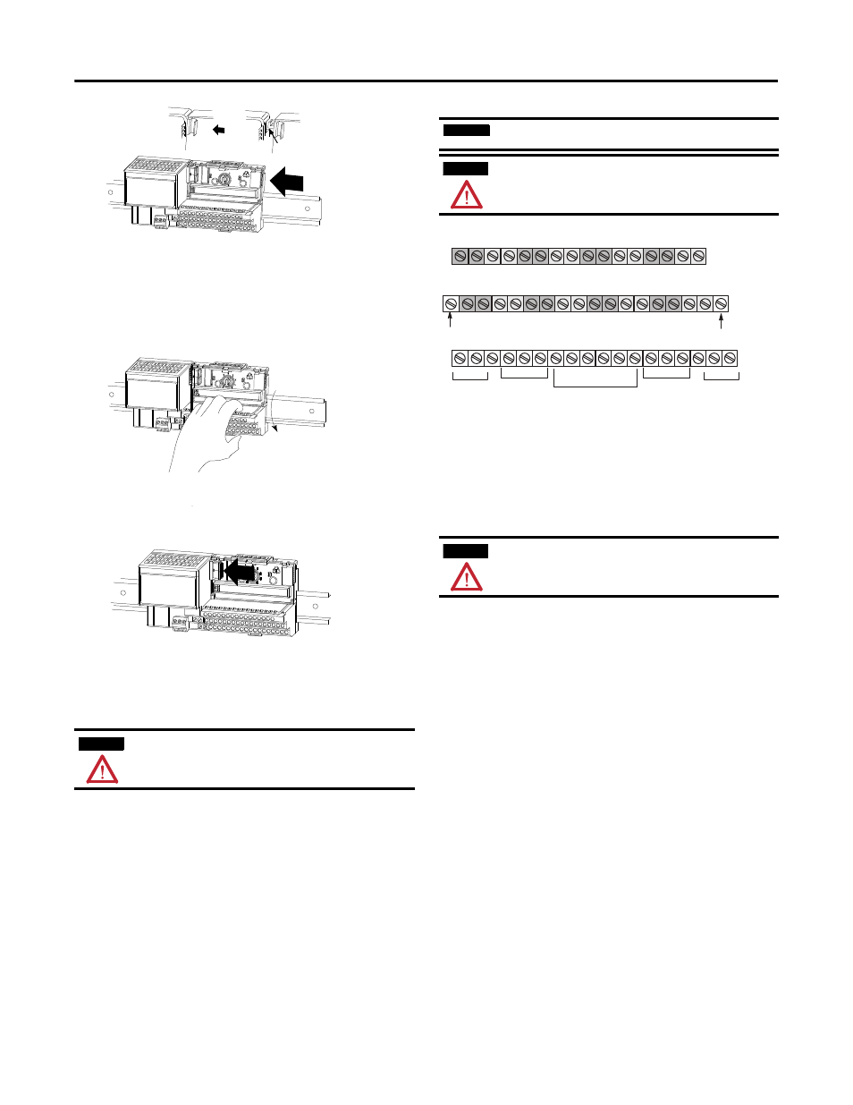
5. Rotate the terminal base onto the DIN rail with the top of the rail
hooked under the lip on the rear of the terminal base. Use caution to
make sure that the female FlexBus connector does not strike any
of the pins in the mating connector.
6. Refer to the installation instructions for specific wiring information
for the module you are installing in this terminal base.
7. Repeat the above steps to install the next terminal base.
Wire Connections for the 1794-TB3GT
ATTENTION
When using FLEX I/O modules in a high-vibration installation,
especially when mounting the DIN rail vertically, use DIN-rail locks
(A-B part number 1492-EA35) to prevent accidental separation of the
terminal block units.
C
Make sure the hook (C) on the terminal base slides under the
edge of the adapter and the FlexBus connector is fully retracted.
Slide the terminal base over, tight against the adapter.
Press down on the terminal base to lock it on the DIN rail. If the
terminal base does not lock into place, use a screwdriver or
similar device to open the locking tab, press down on the base,
and release the locking lever to lock the base in place.
Gently push the FlexBus connector into the side of the side
of the adapter to complete the backplane connection.
IMPORTANT
The 1794-TB3GT terminal base is for use with 1794-IRT8 and
1794-IRT8XT, Series B modules only.
ATTENTION
Do not wire more than 2 conductors on any single terminal.
ATTENTION
The wiring on this base unit is different from other terminal base
units in FLEX I/O. Make certain that connections are correct before
applying power.
17
18
19
20
21
22
23
24
25
26
27
28
29
30
31
32
33
0
1
2
3
4
5
6
7
8
9
10
11
12
13
14
15
16
35
36
37
38
39
40
41
42
43
44
45
46
47
48
49
50
51
34
Ch0
Ch4
24V DC
Supply
In
d
n
G
d
n
G
24V DC
Supply
Out
+V
C
V
+
M
O
COM
6 Chassis
Ground
for Shields
Chassis Ground
Chassis Ground
+
H
+
H
+
H
+
H
+
H
+
H
+
H
+
H
L
-
L
-
L
-
L
-
L
-
L
-
L
-
-
L
Ch1
Ch5
Ch2
Ch6
Ch3
Ch7
CJC1
CJC2
+24V DC = Terminals C-34, C-50
COM = C-35, C-51
Chassis Ground = Terminals B-16, B-33, C-38, C-40…45, C-47
Ch0 = A-0…A-1, B-17…B-18
Channel grouping:
Ch1 = A-4…A-5, B-21…B-22
Ch2 = A-8…A-9, B-25…B-26
Ch4 = A-2…A-3, B-19…B-20
Ch5 = A-6…A-7, B-23…B-24
Ch3 = A-12…A-13, B-29…B-30
Ch7 = A-14…A-15, B-31…B-32
Ch6 = A-10…A-11, B-27…B-28
For daisy-chaining: Supply in - C-34 (+), C-35 (-)
Supply out - C-50 (+), C-51 (-)
CJC1 tail = A1
CJC2 tail = A14