North american hazardous location approval, Mount the terminal base unit on a din rail – Rockwell Automation 1794-TB3GT Flex I/O Terminal Base Units Installation Instructions User Manual
Page 2
2 FLEX I/O Grounded Cage Clamp Temperature Terminal Base Unit
Publication 1794-IN133A-EN-P - May 2012
North American Hazardous Location Approval
The following terminal bases are Hazardous Location approved: 1794-TB3GT
FLEX I/O Grounded Cage Clamp Temperature Terminal Base
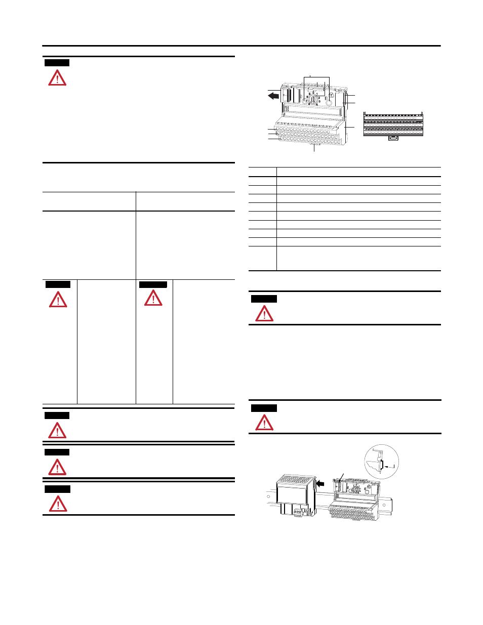
Mount the Terminal Base Unit on a DIN Rail
1. Remove the cover plug (if used) in the male connector of the unit to
which you are connecting this terminal base unit.
2. Check to make sure the 16 pins in the male connector on the adjacent
device are straight and in line so that the mating female connector on
this terminal base unit will mate correctly.
3. Make certain the female connector (B) is fully retracted.
4. Position the terminal base unit on the (35 x 7.5 x 1 mm) top-hat DIN
rail (A) (Allen-Bradley part number 199-DR1).
WARNING
Observe the following additional Zone 2 certification requirements.
•
This equipment is not resistant to sunlight or other sources of UV
radiation.
•
This equipment must be installed in an enclosure providing at
least IP54 protection when applied in Zone 2 environments.
•
This equipment shall be used within its specified ratings defined
by Rockwell Automation.
•
Provision shall be made to prevent the rated voltage from being
exceeded by transient disturbances of more than 40% when
applied in Zone 2 environments.
•
Secure any external connections that mate to this equipment by
using screws, sliding latches, threaded connectors, or other
means provided with this product.
•
Do not disconnect equipment unless power has been removed or
the area is known to be nonhazardous.
The following information applies
when operating this equipment in
hazardous locations:
Informations sur l'utilisation de cet
équipement en environnements
dangereux:
Products marked "CL I, DIV 2, GP A, B, C, D" are
suitable for use in Class I Division 2 Groups A, B, C,
D, Hazardous Locations and nonhazardous
locations only. Each product is supplied with
markings on the rating nameplate indicating the
hazardous location temperature code. When
combining products within a system, the most
adverse temperature code (lowest "T" number) may
be used to help determine the overall temperature
code of the system. Combinations of equipment in
your system are subject to investigation by the
local Authority Having Jurisdiction at the time of
installation.
Les produits marqués "CL I, DIV 2, GP A, B, C, D" ne
conviennent qu'à une utilisation en environnements
de Classe I Division 2 Groupes A, B, C, D dangereux et
non dangereux. Chaque produit est livré avec des
marquages sur sa plaque d'identification qui indiquent
le code de température pour les environnements
dangereux. Lorsque plusieurs produits sont combinés
dans un système, le code de température le plus
défavorable (code de température le plus faible) peut
être utilisé pour déterminer le code de température
global du système. Les combinaisons d'équipements
dans le système sont sujettes à inspection par les
autorités locales qualifiées au moment de
l'installation.
WARNING
EXPLOSION HAZARD
• Do not disconnect
equipment unless power
has been removed or the
area is known to be
nonhazardous.
• Do not disconnect
connections to this
equipment unless power
has been removed or the
area is known to be
nonhazardous. Secure any
external connections that
mate to this equipment by
using screws, sliding
latches, threaded
connectors, or other means
provided with this product.
• Substitution of components
may impair suitability for
Class I, Division 2.
• If this product contains
batteries, they must only be
changed in an area known
to be nonhazardous.
AVERTISSEMENT
RISQUE D’EXPLOSION
• Couper le courant ou s'assurer
que l'environnement est
classé non dangereux avant
de débrancher l'équipement.
• Couper le courant ou s'assurer
que l'environnement est
classé non dangereux avant
de débrancher les
connecteurs. Fixer tous les
connecteurs externes reliés à
cet équipement à l'aide de vis,
loquets coulissants,
connecteurs filetés ou autres
moyens fournis avec ce
produit.
• LLa substitution de
composants peut rendre cet
équipement inadapté à une
utilisation en environnement
de Classe I, Division 2.
• S'assurer que l'environnement
est classé non dangereux
avant de changer les piles.
WARNING
When used in a Class I, Division 2, hazardous location, this
equipment must be mounted in a suitable enclosure with proper
wiring method that complies with the governing electrical codes.
WARNING
If you connect or disconnect wiring while the field-side power is on,
an electrical arc can occur. This could cause an explosion in
hazardous location installations. Be sure that power is removed or the
area is nonhazardous before proceeding.
ATTENTION
For Class I Division 2 applications, use only Class I Division 2 listed or
recognized accessories and modules approved for use within the
1794 platform.
Description
1
Female FlexBus connector
2
Mounting holes for panel mounting
3
Module locking latch
4
Keyswitch - set to the position required for the installed module
5
Male FlexBus connector
6
Cover plug for male FlexBus connector
7
Terminal base unit
8
Locking tab
9…11
Input/output terminal strips for connecting inputs/output wiring,
commons, power connections, customer power supplies, chassis
grounds
ATTENTION
During mounting of all devices, be sure that all debris (such as metal
chips or wire strands) is kept from falling into the module. Debris that
falls into the module could cause damage upon application of power.
ATTENTION
Do not force the terminal base into the adjacent base/adapter.
Forcing the units together can bend or break the hook and allow the
units to separate and break communication over the backplane.
1794-TB3GT
1
2
3 4
5
6
7
8
9
10
11
A
B
A
C
DIN Rail
Position the terminal base at a slight angle and hook it
over the top of the DIN rail.