I/o memory mapping, Wire size and terminal screw torque, Output data file – Rockwell Automation 1769-OF8V Compact Analog Output Module User Manual
Page 12
12 Compact 1769-OF8V Analog Output Module
Publication 1769-IN066D-EN-P - June 2010
Wire Size and Terminal Screw Torque
Each terminal accepts up to two wires with the following restrictions:
I/O Memory Mapping
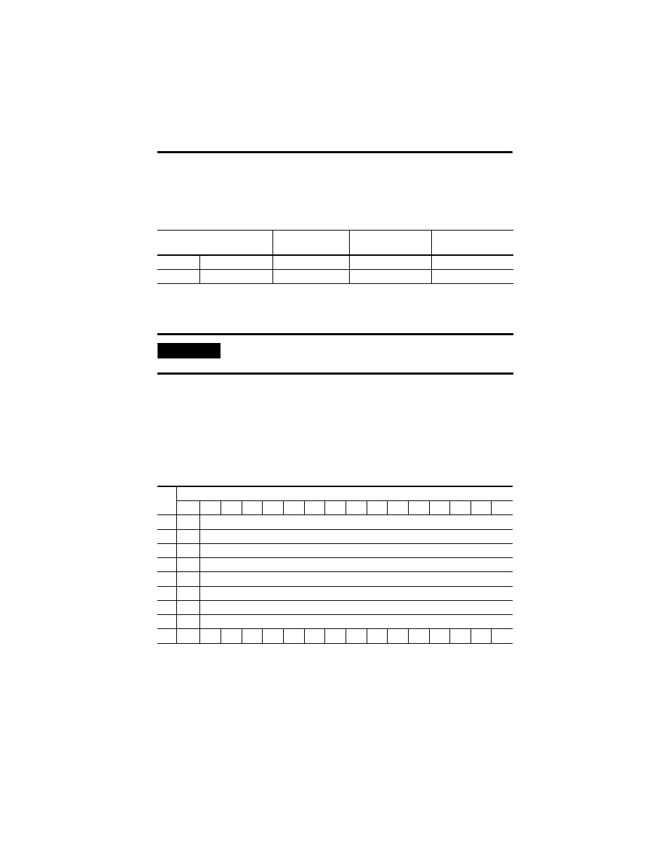
Output Data File
For each module, slot x, words 0-7 in the output data file contain the channel 0 through
channel 7 output data. Word 8 is used to unlatch any alarm condition that has been latched.
Refer to the Compact™ Analog I/O User Manual, publication number 1769-UM002 for
additional details.
• SGN = Sign bit in two’s complement format.
• UU = Unlatch under-range (or low-clamp exceeded) alarm.
• UO = Unlatch over-range (or high-clamp exceeded) alarm.
Wire Type
Wire Size
Terminal Screw
Torque
Retaining Screw
Torque
Solid
Cu-90°C (194°F)
#14 to #22 AWG
0.68 Nm (6 in-lbs)
0.46 Nm (4.1 in-lbs)
Stranded
Cu-90°C (194°F)
#16 to #22 AWG
0.68 Nm (6 in-lbs)
0.46 Nm (4.1 in-lbs)
IMPORTANT
If you are using RSLogix 5000, version 15, please refer to RSLogix 5000,
Version 15, Controller Tags on page 17.
Wo
rd
Bit Position
15
14
13
12
11
10
9
8
7
6
5
4
3
2
1
0
0
SGN
Analog Output Data Channel 0
1
SGN
Analog Output Data Channel 1
2
SGN
Analog Output Data Channel 2
3
SGN
Analog Output Data Channel 3
4
SGN
Analog Output Data Channel 4
5
SGN
Analog Output Data Channel 5
6
SGN
Analog Output Data Channel 6
7
SGN
Analog Output Data Channel 7
8
UU7
UO7 UU6 UO6 UU5 UO5 UU4 UO4 UU3 UO3 UU2 UO2 UU1 UO1 UU0 UO0