Rockwell Automation 1794-IA8_IA8I_IA16 FLEX I/O ac Input Modules Installation Instructions User Manual
Page 3
3
Publication 1794-IN102B-EN-P - June 2004
1794-TB2, -TB3 and -TB3S Terminal Base Wiring for 1794-IA8,
IA8K and -IA16
1794-TBN Terminal Base Wiring for 1794-IA8, IA8K
and -IA16
Connecting Wiring for the 1794-IA16
1. For 1794-TB3, or -TB3S - Connect individual input wiring to
numbered terminals on the 0-15 row (A) as indicated in the table
below .
For 1794-TBN - Connect individual input wiring to even numbered
terminals on the 16-33 row (B), and to the odd numbered terminals
on the 34-51 row (C) as indicated in the table below.
2. For 1794-TB3, or -TB3S - Connect the associated 120V ac power
lead (L1) of the input device to the corresponding terminals on the
34-51 row (C) for each input as indicated in the table below. (The
120V power terminals of row (C) are internally connected together.)
For 1794-TBN - An external terminal strip is needed to distribute
120V ac power (L1) to each device.
3. Connect 120V ac power (L1)to terminal 34 on the 34-51 row (C).
4. Connect 120V ac common (L2) to terminal 16 on the 16-33 row (B).
5. If daisychaining power to the next terminal base, connect a jumper
from terminal 51 (+120V ac L1) on this base unit to terminal 34 on
the next base unit.
6. If continuing ac common to the next base unit, connect a jumper
from terminal 33 (120V common L2) on this base unit to terminal 16
on the next base unit.
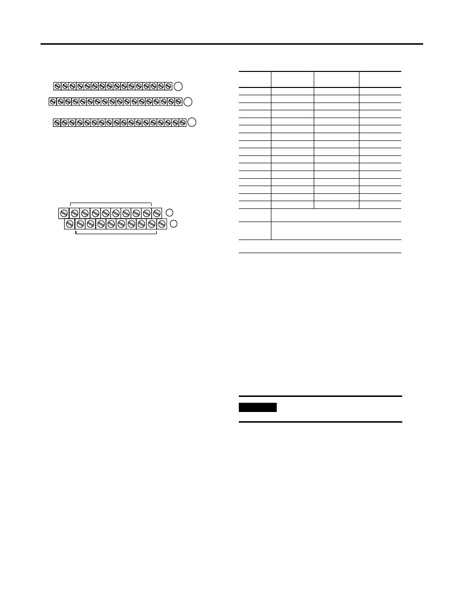
Terminal Base Wiring for 1794-IA16
Connecting Wiring for the 1794-IA8I
1. For 1794-TB2, -TB3, or -TB3S - Connect individual input wiring to
even numbered terminals on the 0-15 row (A) as indicated in the table
below .
For 1794-TBN - Connect individual input wiring to even numbered
terminals 0-14 on the 16-33 row (B) as indicated in the table below.
2. For 1794-TB2, -TB3, or -TB3S - Connect the associated 120V ac
common (L2) of the isolated supply to the corresponding odd
numbered terminals on the 0-15 row A for each input as indicated in
the table below.
For 1794-TBN - Connect the associated 120V ac common lead (L2)
of the isolated supply to the corresponding odd numbered terminal
1-15 on the 34-51 row (C) as indicated in the table below.
17 18 19 20 21 22 23 24 25 26 27 28 29 30 31 32 33
0 1 2 3 4 5 6 7 8 9 10 11 12 13 14 15
16
35 36 37 38 39 40 41 42 43 44 45 46 47 48 49 50 51
34
Inputs
Commons
(1794-TB3 shown)
L2
L1
Voltage
A
B
C
L2
Connect 120V ac L1 power to terminal C-34
Connect 120V ac common L2 to terminal B-16
Use B-33 and C-51 for daisychaining to the next terminal base unit
L1
(Terminals C-35 thru C-50 not available on the 1794-TB2.)
16
0
1
2
3
4
5
6
7
8
9
10
11
12
13
14
15
51
33
34
L1
L2
L1
L2
B
C
Even Numbered I/O Terminals 0 thru 14
Odd Numbered I/O Terminals 1 thru 15
(1794-TBN shown)
L1 = 120V ac - Connect to terminal C-34
L2 = 120V ac common - Connect to terminal B-16
Use B-33 and C-51 for daisychaining to the next terminal base unit
Input
Channel
Input Terminal
1794-TB3, -TB3S
Input Terminal
1794-TBN
120V ac
Supply (L1)
1
Input 0
A-0
B-0
C-35
Input 1
A-1
C-1
C-36
Input 2
A-2
B-2
C-37
Input 3
A-3
C-3
C-38
Input 4
A-4
B-4
C-39
Input 5
A-5
C-5
C-40
Input 6
A-6
B-6
C-41
Input 7
A-7
C-7
C-42
Input 8
A-8
B-8
C-43
Input 9
A-9
C-9
C-44
Input 10
A-10
B-10
C-45
Input 11
A-11
C-11
C-46
Input 12
A-12
B-12
C-47
Input 13
A-13
C-13
C-48
Input 14
A-14
B-14
C-49
Input 15
A-15
C-15
C-50
120V ac L1
Power terminals C-34 thru C-51 (C-34 and C-51 on -TBN) are
internally connected together. Connect 120V ac L1 to C-34
120V ac L2
Common terminals B-16 thru B-33 (B-16 and B-33 for -TBN) are
internally connected together. Connect 120V ac common L2 to
terminal B-16
1
When using the 1794-TBN, an external terminal strip is needed to connect the 120V ac power
connections.
IMPORTANT
Individual isolated 120V ac L1 power leads must
be run externally to each of the input devices.