Installation, Link attenuation, Power supply – Rockwell Automation 1785-TR10BT Twisted Pair Transceiver Installation Instructions User Manual
Page 3: Sqe test, For additional information
1785-5.20 - January 1999
Twisted Pair Transceiver
3
Installation
Link Attenuation
ISO/IEC 8802-3 (10BASE-T) specifies that the link attenuation of a single
cable segment must not exceed 11.5 dB at frequencies between 5 and 10
MHz (ZL = 100
Ω
). This value includes
•
the attenuation of the twisted pair cable
•
connector attenuation
•
reflection attenuations as the result of adaption errors of the various
components belonging to the single cable segment, e.g., patch panels in
which twisted pair cables are connected to each other which, within the
scope of the tolerance, have differing characteristic impedance values at
the coupling point
Power Supply
The operating voltage (+12 V) is taken from the connected device via the
15-pin Sub-D socket of the AUI interface.
SQE Test
The slide switch on the top of the transceiver case is used to activate and
deactivate the SQE test. Before placing the transceiver in operation, you
should check to see whether the connected device requires the SQE test to
be on or off. As delivered from the factory, the SQE test is on.
For Additional Information
For standards information, go to
http://www.ieee.org/
. To download a .PDF
copy of this publication, go to
http://www.theautomationbookstore.com/
.
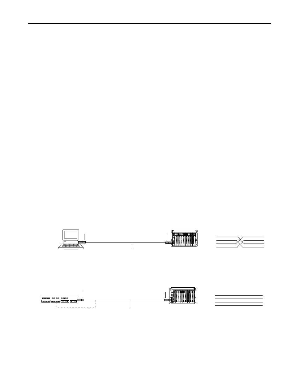
Connecting two devices
Pin assignments of the RJ45 to RJ45
connecting lead
RJ45
RJ45
1
2
3
6
1
2
3
6
PC
PLC5E
1785-TR10BT
1785-TR10BT
Twisted pair cable (100
Ω
)
with RJ45 connectors
Connecting to an unshielded twisted pair interface card (hub, switch)
Pin assignments of the RJ45 to RJ45
connecting lead
RJ45
RJ45
1
2
3
6
1
2
3
6
Hub
PLC5E
1785-TR10BT
1785-TR10BT
or direct-connected to RJ45
Twisted pair cable (100
Ω
)
with RJ45 connectors