Description – Rockwell Automation 1785-TR10BT Twisted Pair Transceiver Installation Instructions User Manual
Page 2
1785-5.20 - January 1999
2
Twisted Pair Transceiver
Description
The 1785-TR10BT twisted pair transceiver can be connected to the AUI
interface of a device either directly or via an AUI cable. It is connected to
the twisted pair cable by a 8-pin RJ45 socket.
The twisted pair transceiver offers these functions according to IEEE 802.3
10BASE-T:
•
indication via a LED of data transmission and reception through the
twisted pair cable
•
detection of data collisions in the network and reporting them to the
terminal equipment as well as indicating them by a LED
•
ability to enable/disable the SQE test: at the end of every transmit
operation, a short collision signal (heart beat) approx. 1 µs long is sent to
monitor the electronics
•
jabber control and display: protecting the network form data packets that
are too long (> 20 ms)
•
link control and display: continious moni-toring the twisted pair cable
segment with link test pulses for short-circuits or idling
•
auto polarity exchange (APX) and display: the polarity is reversed
automatically if the receiving wire pair is connected incorreclty (RD+
and RD- switched round)
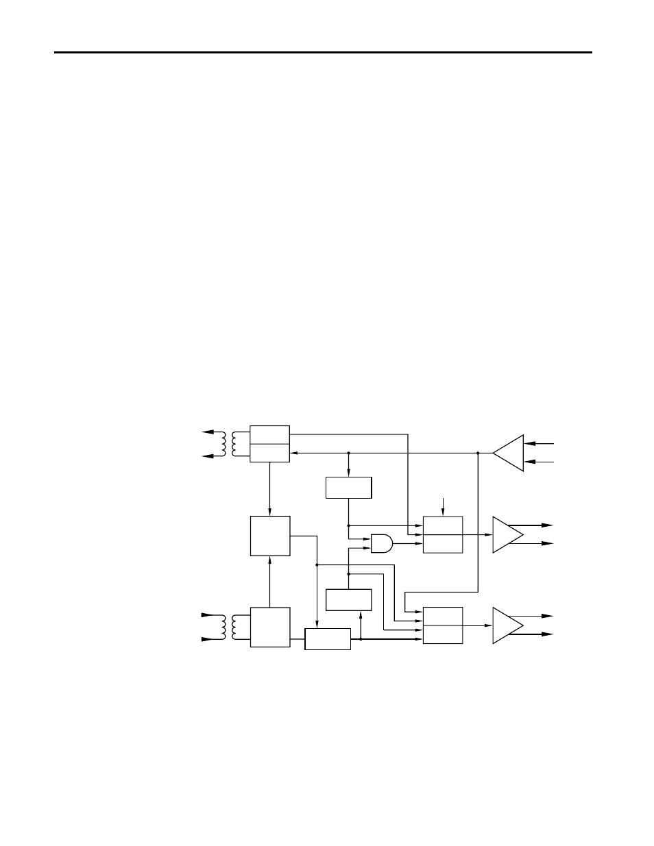
DO
CI
DI
SQE-Test
Generator
Osc.
ENABLE/
DISABLE
Collision
Tx-Packet
Detect
Link
Status
Control
Rx-Data
Tx-Data
Jabber
Protect
Loopback
Data
Rx-Data
Auto Polarity
Exchange
Rx-Packet
Detect
DISABLE
ENABLE
10BAS
E
-T
In
terf
ace
(R
J4
5
co
n
n
ect
or
)
A
U
I In
te
rf
ac
e
(15-pi
n sub-
D c
onnec
tor
)