Configuration data file – Rockwell Automation 1769-IF16V Compact High Density Analog Voltage Input Module User Manual
Page 17
Compact High-density Analog Voltage Input Module 17
Publication 1769-IN086A-EN-P - August 2008
The bits are defined as follows:
•
SGN = Sign bit in 2’s complement format.
•
Nu = Not Used. Bit set to 0.
•
S
x = General Status bit for input channels 0…15.
•
O
x = Over range flag bits for input channels 0…15.
•
U
x = Under range flag bits for input channels 0…15.
•
H
x = High Alarm flag bits for input channels 0…15.
•
L
x = Low Alarm flag bits for input channels 0…15.
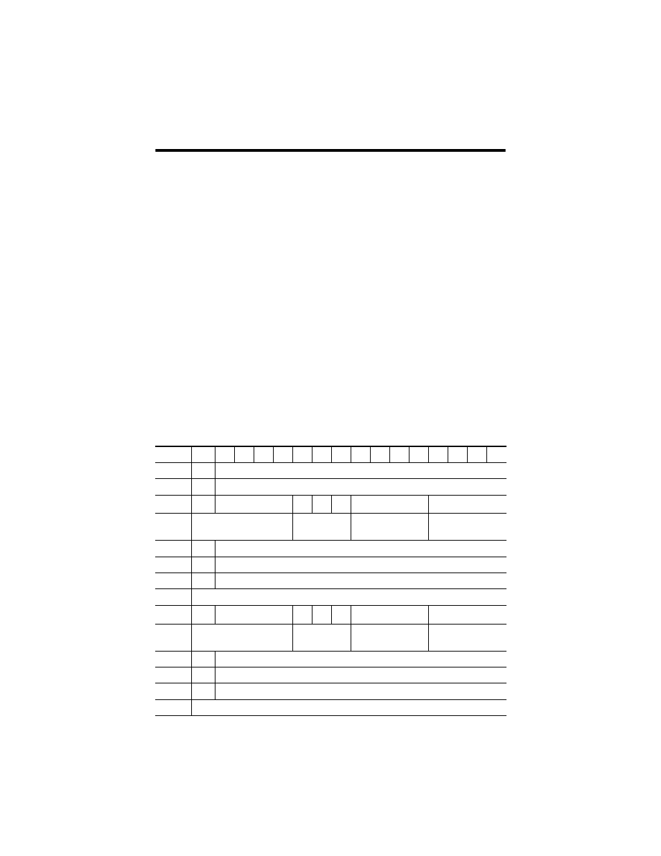
Configuration Data File
The manipulation of bits from this file is normally done with programming software
(for example, RSLogix 5000, RSLogix 500, or RSNetWorx for DeviceNet software)
during initial configuration of the system. In that case, graphical screens provided
by the programming software simplify configuration.
Some systems, like the 1769-ADN DeviceNet adapter system, also allow the bits to
be altered as part of the control program using communication rungs. In that case,
it is necessary to understand the bit arrangement.
Configuration Data Array
Word/Bit 15
14
13
12
11
10
09
08
07
06
05
04
03
02
01
00
Word 0
0
Real Time Sample Value
Word 1
ETS
Reserved
Word 2
EC
Reserved
EA
AL
Reserved
Input Filter Sel Ch0
Word 3
Reserved
Input Data
Format Ch0
Reserved
Input Type/Range
Select Ch0
Word 4
SGN Process Alarm High Data Value Channel 0
Word 5
SGN Process Alarm Low Data Value Channel 0
Word 6
SGN Alarm Dead Band Value Channel 0
Word 7
Reserved
Word 8
EC
Reserved
EA
AL
Reserved
Input Filter Sel Ch1
Word 9
Reserved
Input Data
Format Ch1
Reserved
Input Type/Range
Select Ch1
Word 10 SGN Process Alarm High Data Value Channel 1
Word 11 SGN Process Alarm Low Data Value Channel 1
Word 12 SGN Alarm Dead Band Value Channel 1
Word 13 Reserved