Use the dimensional template – Rockwell Automation 1769-IF16V Compact High Density Analog Voltage Input Module User Manual
Page 10
10
Compact High-density Analog Voltage Input Module
Publication 1769-IN086A-EN-P - August 2008
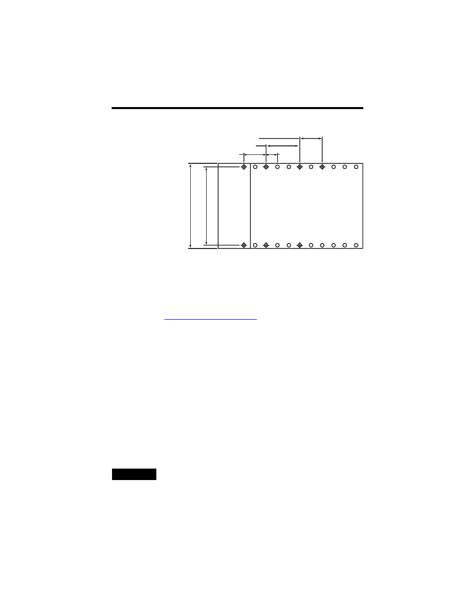
Use the Dimensional Template
Locate holes every 17.5 mm (0.689 in.) to allow for a mix of single-wide and
one-and-a-half-wide modules (for example, the 1769-OA16 module).
Use Modules as a Template
This procedure lets you use the assembled modules as a template for drilling holes
in the panel. See
if you have sophisticated panel
mounting equipment.
On a clean work surface, assemble no more than three modules.
Due to module-mounting hole tolerance, it is important to follow this procedure.
1. Using the assembled modules as a template, carefully mark the center of all
module-mounting holes on the panel.
2. Return the assembled modules to the clean work surface, including any
previously mounted modules.
3. Drill and tap the mounting holes for the recommended M4 or #8 screws.
4. Place the modules back on the panel, and check for proper hole alignment.
5. Attach the modules to the panel using the mounting screws.
6. Repeat steps 1…6 for any remaining modules.
TIP
If you are mounting more modules, mount only the last one of this
group and put the others aside. This reduces the remounting time
during drilling and tapping of the next group.
Spacing for single-wide modules 35 mm (1.378 in.)
Spacing for one-and-a-half wide modules 52.5 mm (2.067 in.)
Refer to host controller documentation for this dimension.
NOTE: Overall spacing
tolerance ±0.44 mm (0.016 in.)