Key the backplane connector, Setting the relay output jumpers – Rockwell Automation 1771-OWN Selectable Contact Installation Instructions User Manual
Page 5
Selectable Contact Output Module
5
Publication 1771-IN037B-EN-P - July 2002
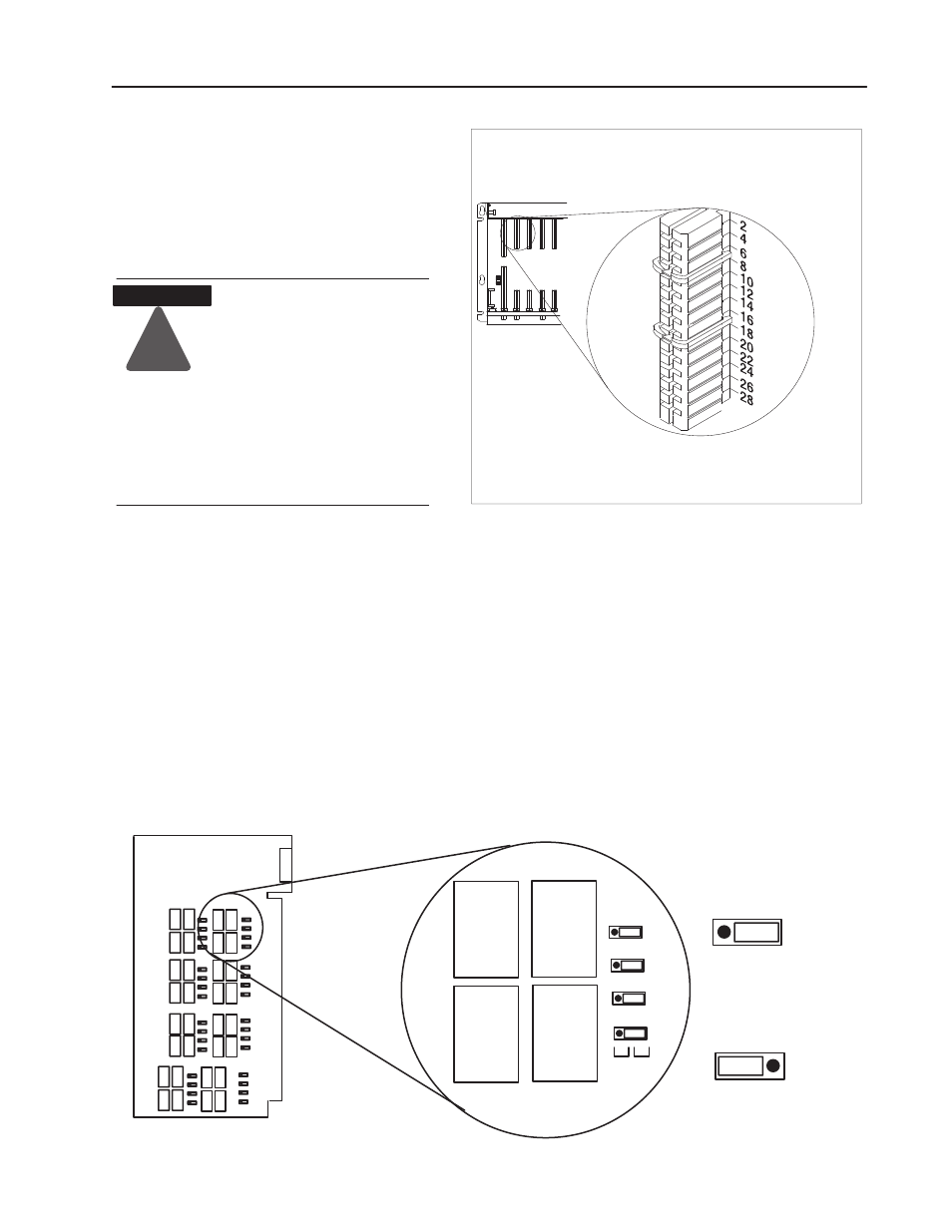
Key the Backplane
Connector
Place your module in any slot in the chassis
except the leftmost slot which is reserved
for processors or adapters.
Observe the following
precautions when inserting or
removing keys:
•
insert or remove keys with
your fingers
•
make sure that key placement
is correct
Incorrect keying or the use of a
tool can result in damage to the
backplane connector and
possible system faults.
!
ATTENTION
Position the keying bands in the backplane connectors to correspond to
the key slots on the module.
Place the keying bands:
- between 6 and8
- between 16 and18
You can change the position of these bands if
subsequent system design and rewiring makes
insertion of a different type of module necessary.
Upper
Connector
11022ĆI
I/O chassis
When the output image table bit at the address corresponding to any
output is energized (set to 1), the corresponding relay contact is
closed or opened, respective to the jumper setting.
All outputs are individually selectable for either normally-open or
normally-closed operation. They are pre-set for normally-open
operation at the factory. To reset any jumper, proceed as follows:
1. Remove the 4 screws from the side cover and separate the circuit
board from the 2 covers.
2. Move the jumper to the desired position. Jumpers are identified
by jumper number and use (N.O. or N.C.). Refer to Table A for
jumper and terminal identifications.
N.O.
N.C.
L-02
L-00
L-04
L-06
N.O.
N.C.
Normally Open
Normally Closed
PrintedCircuit Board
N.O.
N.C.
RY10
RY
9
RY
2
RY
1
10538ĆI
Setting the Relay Output
Jumpers