Rio link wiring – Rockwell Automation 1747-SN Remote I/O Scanner User Manual
Page 10
10 Remote I/O Scanner
Publication 1747-IN060D-EN-P - November 2002
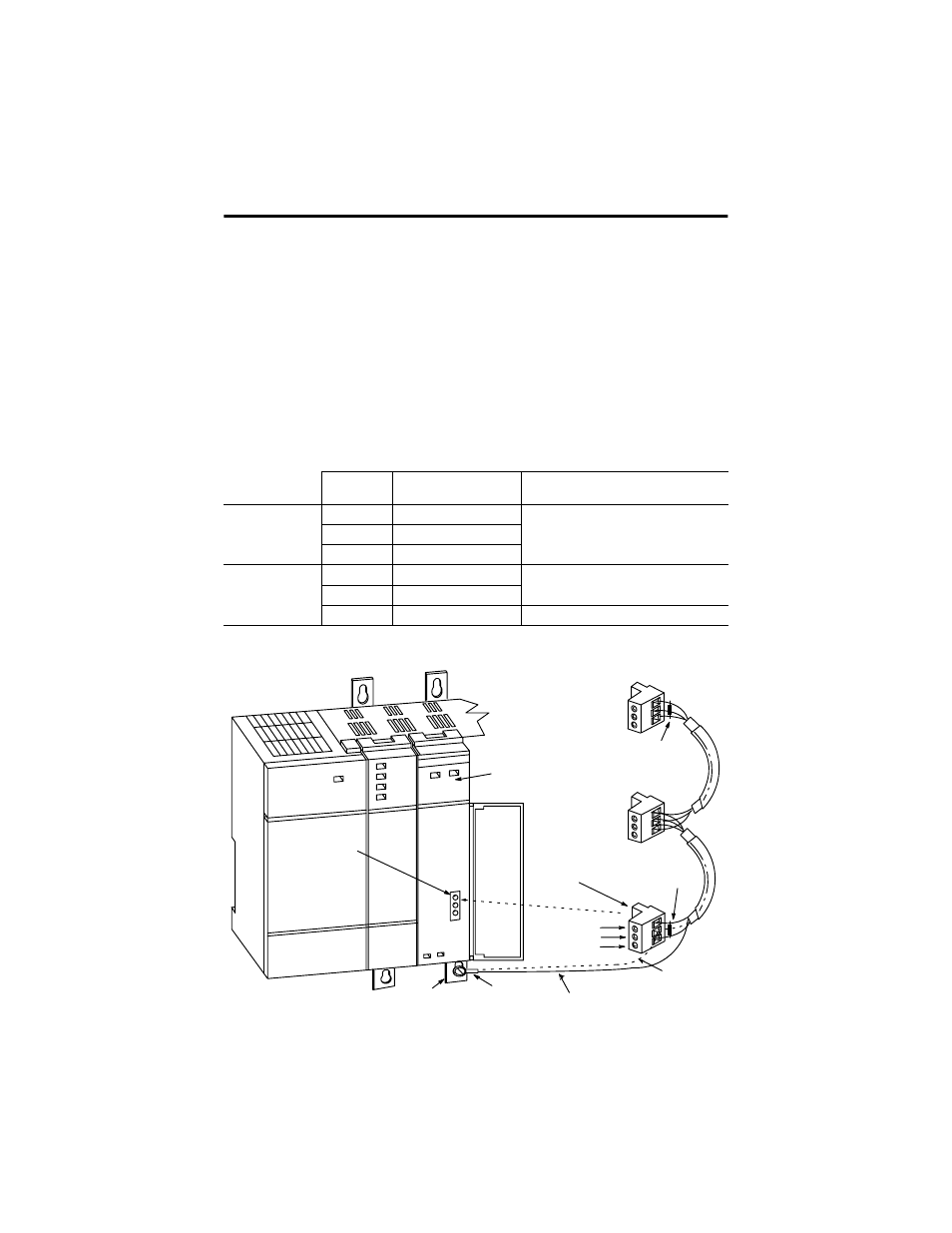
RIO Link Wiring
The scanner is connected to other devices on the RIO link in a daisy-chain (serial)
configuration. There are no restrictions governing the space between each device,
provided the maximum cable distance (Belden 9463) is not exceeded. A 1/2 watt
terminating resistor (included with the module) must be attached across line 1 and
line 2 of the connectors at each end (scanner and last physical device) of the RIO
link. The size of the resistor depends on the baud rate and extended node
capability, as shown in the table below.
Note: To use extended node, all devices on the RIO link must support it. Refer to
each device’s user manual.
Baud Rate
Max. Cable Distance
(Belden 9463)
Resistor Size
Using Extended
Node Capability
57.6K baud
3048 m (10,000 ft.)
82
Ω
1/2 Watt Gray-Red-Black-Gold
115.2K baud
1524 m (5,000 ft.)
230.4K baud
762 m (2,500 ft.)
Not Using
Extended Node
Capability
57.6K baud
3048 m (10,000 ft.)
150
Ω
1/2 Watt Brown-Green-Brown-Gold
115.2K baud
1524 m (5,000 ft.)
230.4K baud
762 m (2,500 ft.)
82
Ω
1/2 Watt Gray-Red-Black-Gold
RIO Scanner
RIO Link
Connector
Terminating Resistor Last
Physical Device End
Terminating Resistor
Scanner End
Shield Drain Wire
(For Series A Retrofits)
Shield Drain Wire
(For New Series B Installations)
Ring Lug
Chassis Mounting
Bracket
RIO Link
Connector
Line 1 – Blue
Shield – Shield
Line 2 – Clear