Interpreting the status indicators, Replacing the fuses – Rockwell Automation 1771-OQ/B Isolated 24V dc Output Module Installation Instructions User Manual
Page 8
Publication 1771-IN081B-EN-P - June 2004
8 Isolated 24V dc Output Module
Interpreting the Status
Indicators
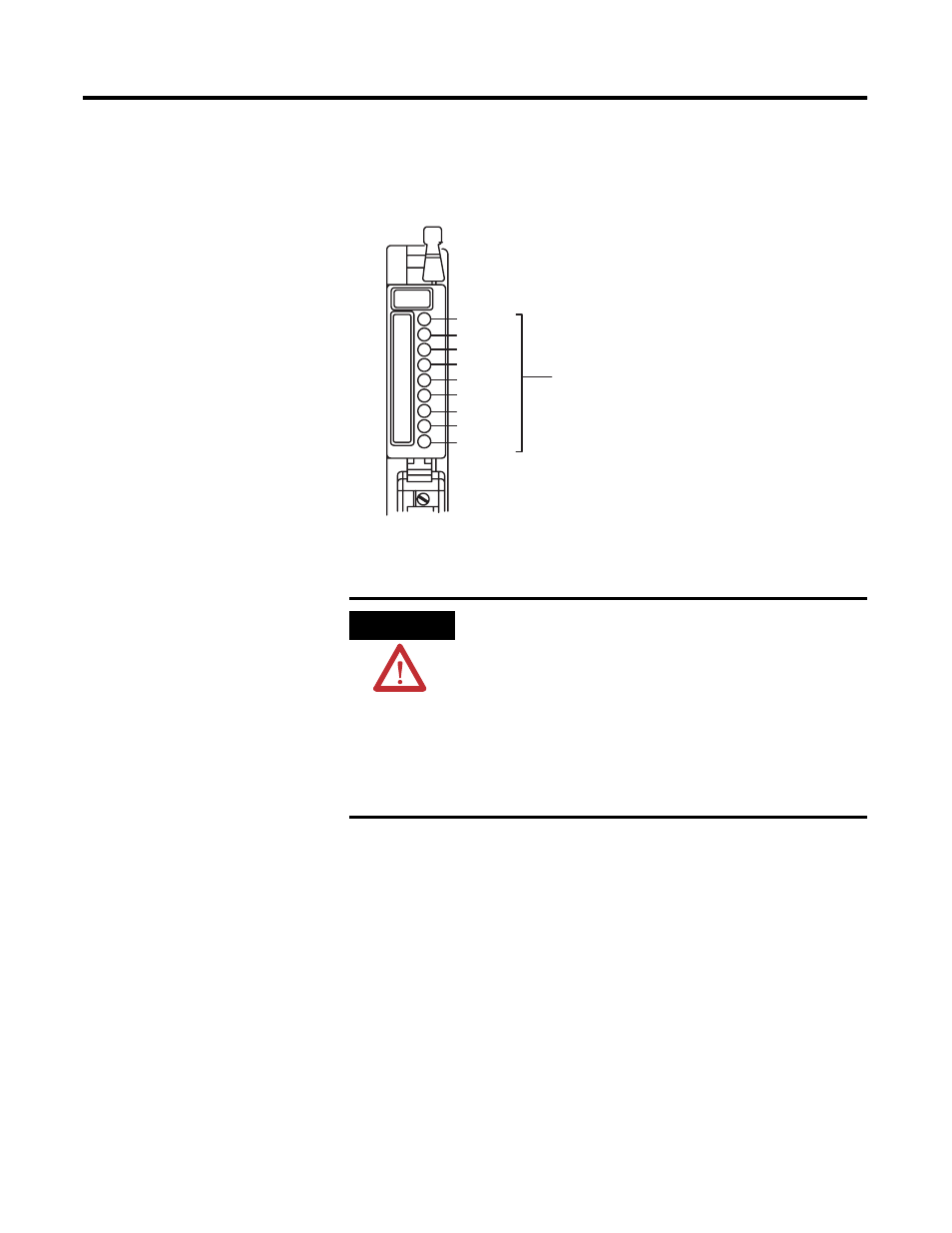
The front panel of your module contains 8 red status indicators (below). The
red status indicators are on when the associated output is on.
Replacing the Fuses
To replace a blown fuse, proceed as follows:
1. Turn off power to the chassis.
2. Remove the module from the I/O chassis.
3. Remove the 2 screws securing the front cover on the unlabelled side of
the module. Note: One fuse protects 2 outputs.
4. Remove the blown fuse from fuse holder, and replace with a 2.5A, 3AG
normal blow fuse.
5. Replace the cover and secure with screws removed in step 3.
6. Reinsert the module into I/O chassis.
7. Turn on power to chassis.
Not used
Output 0
Output 1
Output 2
Output 3
Output 4
Output 5
Output 6
Output 7
Status Indicators
1
1067-I
ATTENTION
Remove power from the 1771 I/O chassis backplane and
field wiring arm before removing or installing an I/O
module.
• Failure to remove power from the backplane or wiring
arm could cause module damage, degradation of
performance, or injury.
• Failure to remove power from the backplane could
cause injury or equipment damage due to possible
unexpected operation.