Modifying the data table – Rockwell Automation 1771-OBDS DC(10-40V)Current Limiting Input Module Installation Instructions User Manual
Page 10
DC (10-40V) Current Limiting Output Module
10
Publication 1771ĆIN033B-EN-P - July 2002
Each output of the module is capable of withstanding a short circuit
condition. When an output is shorted, it will become ”latched off,”
but its corresponding status indicator will remain lighted. Once the
short circuit is removed from that output, the output image table bit
for that output must be reset by ”toggling” the bit off and then back
on. This resumes normal operation. This toggling procedure can be
done several ways, depending on your system setup:
•
modifying the data table
•
switching the programmable controller from RUN to PROGRAM
mode, and back again
•
cycling power to the system.
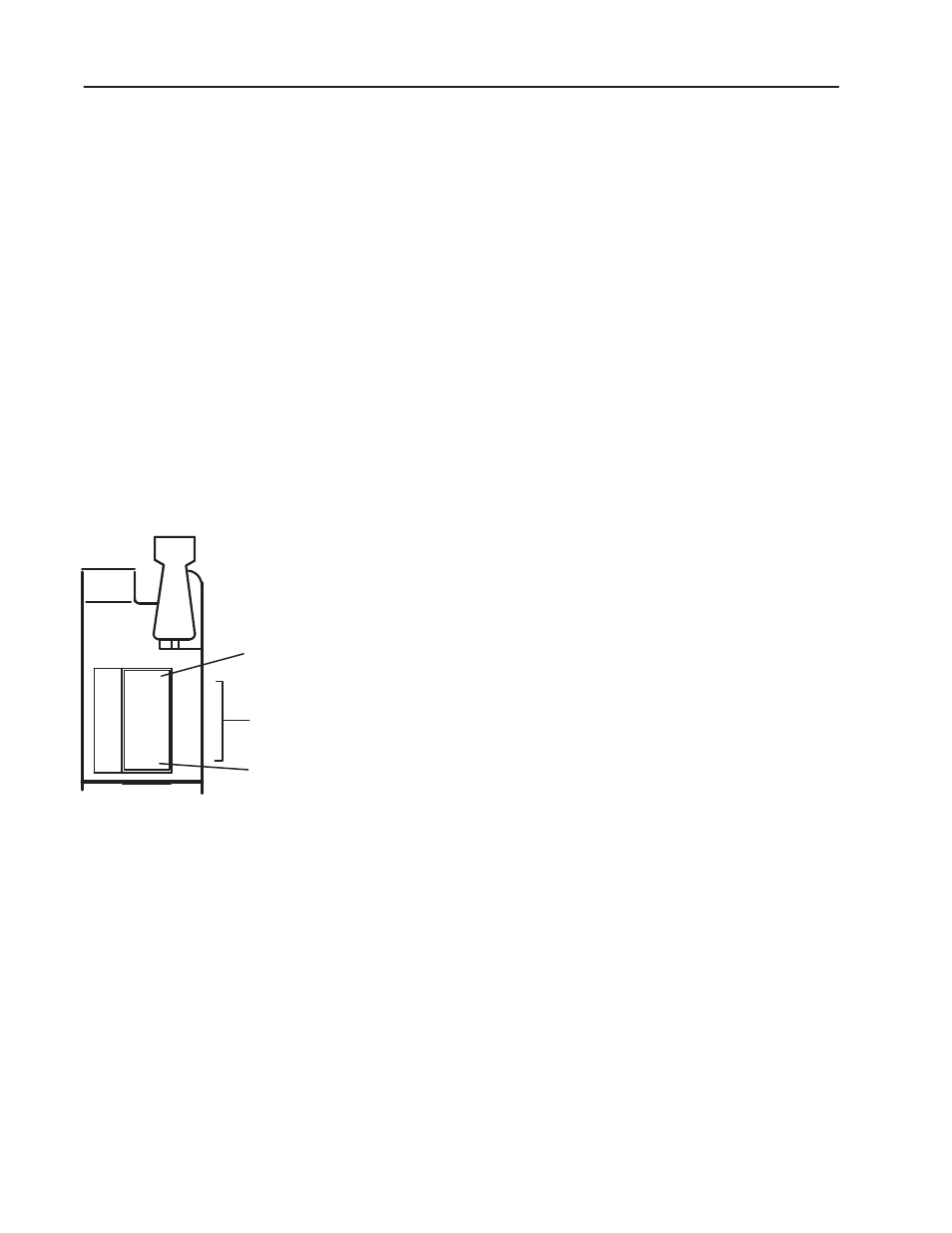
The front panel of your module contains one green module active
indicator, 16 red status indicators and one red fuse blown indicator.
The green module active indicator lights when the module is
powered, the processor keyswitch is on ”run”, and the opto-isolators
and data paths are functioning properly. It turns off if a fault occurs
in the data paths or the opto-isolators. The module then resets its
outputs or sets them to last state.
The module active indicator must be on to properly interpret the red
status indicators. The red status indicators are provided for indication
of individual outputs. They indicate the state to which the transistor
is commanded by the processor and are powered by circuitry within
the module. The indicators will turn on and off as commanded by the
processor. They do not indicate the presence or absence of dc power
at an output terminal. However, all output status indicators will turn
off if the fuse is blown.
The fuse blown indicator turns on when the fuse is blown. When the
fuse blown indicator is lit, check the fuse. After checking the fuse,
make sure the field wiring arm is firmly in place. Do this before
checking the status of the other indicators.
ACTIVE
00
01
02
03
04
05
06
07
10
11
12
13
14
15
16
17
Module Active
Indicator (green)
00 to 17 Status
Indicators (red)
FUSE
Fuse Blown
Indicator (red)
10421ĆI
Short Circuit Protection
Interpreting the Status
Indicators