Specifications – Rockwell Automation 1794-IP4/B INSTL INSTR 24V dc FLEX I/O 4 CHANNEL User Manual
Page 5
5
Publication 1794-IN064D-EN-P - March 2005
Specifications
Specifications
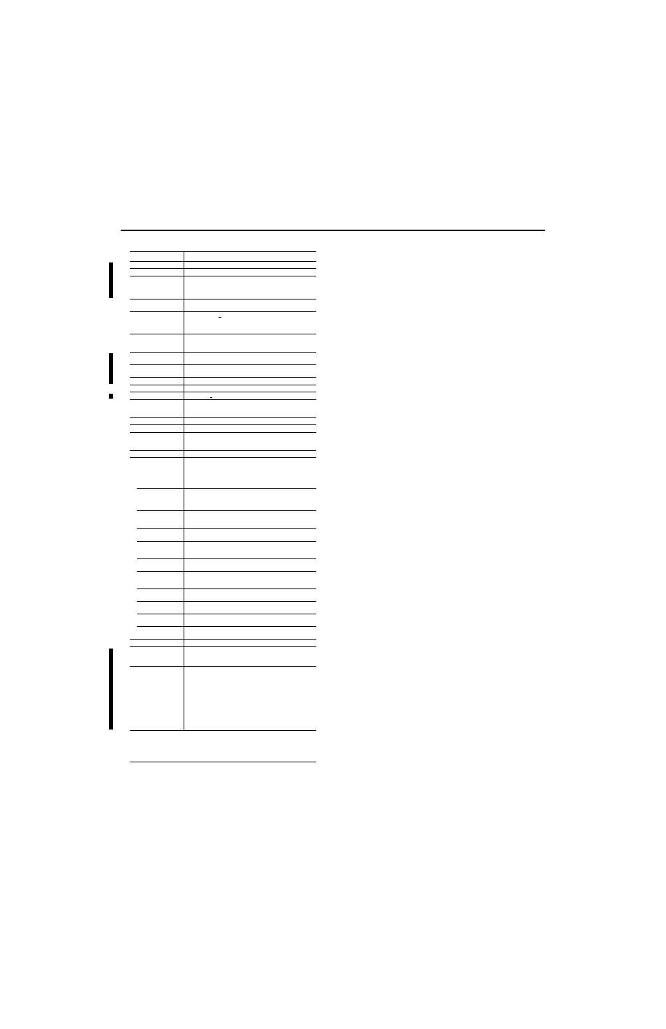
Pulse Counter Module, Cat. No. 1794-IP4
Number of Inputs
4
Module Location
Cat. No. 1794-TB2, -TB3, -TB3S, -TBN
Dimensions (with module
installed in base)
Imperial
Metric
3.7H x 3.7W x 2.7D inches
94H x 94W x 69D mm
Counting Frequency
100kHz maximum - Each signal condition must be stable for at least
2
µs to be recognized
Input Range Input ON
Input OFF
26.4V dc (24V dc +10%) maximum
6V dc minimum
3V dc maximum
-26.4V dc minimum
Input Current (typical)
3mA @ 6V dc
9mA @ 12V dc
15mA @ 24V dc
Data Format
Period read in 1
µs counts with 1 MHz internal clock selected;
0.1
µs counts when 10 MHz internal clock selected.
Overflow
Maximum period is 65 ms when 1 MHz internal clock selected;
maximum period = 6.5 ms when 10 MHz internal clock selected
Isolation Voltage
Tested at 600V ac for 1s
Flexbus Current
5mA at 5V dc
Power Supply (external)
12...24V dc (+10%)
Current Consumption
from external power
supply
150mA @ 12V dc
75mA @ 24V dc
Power Dissipation
5W maximum @ 26.4V dc
Thermal Dissipation
17.1 BTU/hr (maximum) @ 26.4V dc
Indicators (field side
indication, customer
device driven)
1 green/red power/status indicator
8 yellow status indicators
Keyswitch Position
1
Environmental Conditions
Operating
Temperature
IEC 60068-2-1 (Test Ad, Operating Cold),
IEC 60068-2-2 (Test Bd, Operating Dry Heat),
IEC 60068-2-14 (Test Nb, Operating Thermal Shock):
0 to 55°C (32 to 131°F)
Storage Temperature
IEC 60068-2-1 (Test Ab, Unpackaged Nonoperating Cold),
IEC 60068-2-2 (Test Bb, Unpackaged Nonoperating Dry Heat),
IEC 60068-2-14 (Test Na, Unpackaged Nonoperating Thermal Shock):
–40 to 85°C (–40 to 185°F)
Relative Humidity
IEC 60068-2-30 (Test Db, Unpackaged Nonoperating
Damp Heat):
5 to 95% non-condensing
Vibration
IEC60068-2-6 (Test Fc, Operating):
5g @ 10-500Hz
Shock
IEC60068-2-27 (Test Ea, Unpackaged shock):
Operating 30g
Non-operating 50g
Emissions
CISPR 11:
Group 1, Class A (with appropriate enclosure)
ESD Immunity
IEC 61000-4-2:
4kV contact discharges
8kV air discharges
Radiated RF Immunity
IEC 61000-4-3:
10V/m with 1kHz sine-wave 80%AM from 80MHz to 1000MHz
EFT/B Immunity
IEC 61000-4-4:
±2kV at 5kHz on signal ports
Surge Transient
Immunity
IEC 61000-4-5:
±1kV line-earth(CM) on shielded ports
Conducted RF
Immunity
IEC 61000-4-6:
10Vrms with 1kHz sine-wave 80%AM from 150kHz to 80MHz
Enclosure Type Rating
None (open-style)
Conductors
Wire
Length (maximum)
Category
2
Belden 8761
1000ft (304.8m)
2
Certification (when
product is marked)
3
C
-UL-
US
UL Listed Industrial Control Equipment, certified for US and
Canada
C
-UL-
US
UL Listed for Class I, Division 2, Groups A, B, C and D
Hazardous locations certified for US and Canada
CE
European Union 89/336/EEC EMC Directive,
compliant with:
EN 61000-6-4; Industrial Emissions
EN 61000-6-2; Industrial Immunity
EN 61326; Meas./Control/Lab., Industrial Requirements
EN 50082-2; Industrial Immunity
C-Tick - Australian Radiocommunications Act compliant with
AS/NZS CISPR 11, Industrial Emissions
1
Input off-to-on filter time is the time from a valid input signal to recognition by the module. Input on-to-off filter
time is time from the input signal dropping below the valid level to recognition by the module.
2
You use this category information for planning conductor routing. Refer to Allen-Bradley publication 1770-4.1,
Industrial Automation Wiring and Grounding Guidelines.
3
For the latest up-to-date information, see the Product Certification link at www.ab.com for Declarations of
Conformity, Certificates and other certification details. For notification of any additional release notes, refer to
www.ab.com/manuals/.