Installing your pulse counter module – Rockwell Automation 1794-IP4/B INSTL INSTR 24V dc FLEX I/O 4 CHANNEL User Manual
Page 2
2
Publication 1794-IN064D-EN-P - March 2005
Installing Your Pulse Counter Module
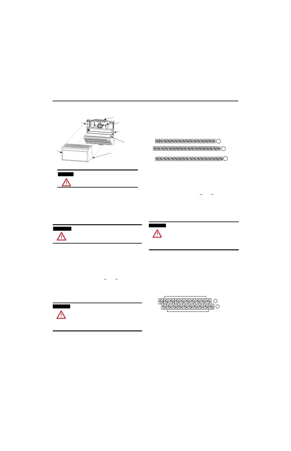
The module mounts on a 1794 terminal base.
1. Rotate the keyswitch (1) on the terminal base (2) clockwise to position
1 as required for this type of module.
2. Make certain the flexbus connector (3) is pushed all the way to the left
to connect with the neighboring termbase/adapter. You cannot install
the module unless the connector is fully extended.
3. Make sure the pins on the bottom of the module are straight so they
will align properly with the connector in the terminal base.
4. Position the module (4) with its alignment bar (5) aligned with the
groove (6) on the terminal base.
5. Press firmly and evenly to seat the module in the terminal base unit.
The module is seated when the latching mechanism (7) is locked into
the module.
Connecting Wiring for the 1794-IP4 (using a 1794-TB2, -TB3 or
-TB3S terminal base unit)
1. Connect individual input wiring (N, N) or (D, D) for each channel to
numbered terminals on the 0-15 row (A) as indicated in the table
below.
2. Connect the associated input common to the corresponding terminal
on the 16-33 row (B) for each input as indicated in the table below.
3. Connect +V dc power to terminal 34 on the 34-51 row (C).
4. Connect dc return to terminal 16 on the 16-33 row (B).
5. If daisychaining power to the next terminal base, connect a jumper
from terminal 51 (+V dc) on this base unit to terminal 34 on the next
base unit.
6. If continuing dc common to the next base unit, connect a jumper
from terminal 33 (common) on this base unit to terminal 16 on the
next base unit.
Connecting Wiring for the 1794-IP4 (using a 1794-TBN terminal
base unit)
1. Connect individual input wiring (N, N) or (D, D) for each channel to
the even-numbered terminals on the 16-33 row (B) as indicated in the
table below.
2. Connect the associated input common to the corresponding
odd-numbered terminal on the 34-51 row (C) for each input as
indicated in the table below.
3. Connect +V dc power to terminal 34 on the 34-51 row (C).
4. Connect dc return to terminal 16 on the 16-33 row (B).
5. If daisychaining power to the next terminal base, connect a jumper
from terminal 51 (+V dc) on this base unit to terminal 34 on the next
base unit.
6. If continuing dc common to the next base unit, connect a jumper
from terminal 33 (common) on this base unit to terminal 16 on the
next base unit.
ATTENTION
During mounting of all devices, be sure that all debris
(metal chips, wire strands, etc.) is kept from falling into
the module. Debris that falls into the module could
cause damage on power up.
WARNING
If you remove or insert the module while the backplane
power is on, an electrical arc can occur. This could cause
an explosion in hazardous location installations. Be sure
that power is removed or the area is nonhazardous before
proceeding.
ATTENTION
Do not connect maximum input voltage simultaneously to
all inputs if the module ambient temperature is expected to
exceed 40°C.
If the ambient temperature is expected to continuously
exceed 40°C, you must limit the input voltage using an
external resistor on each input. A 1k
Ω resistor effectively
limits a 24V sensor signal to about 15V at the input. Do not
limit the input to less than 6V.
1
2
3
4
5
6
7
ATTENTION
Do not connect maximum input voltage simultaneously to
all inputs if the module ambient temperature is expected to
exceed 40°C.
If the ambient temperature is expected to continuously
exceed 40°C, you must limit the input voltage using an
external resistor on each input. A 1kW resistor effectively
limits a 24V sensor signal to about 15V at the input. Do not
limit the input to less than 6V.
17 18 19 20 21 22 23 24 25 26 27 28 29 30 31 32 33
0 1 2 3 4 5 6 7 8 9 10 11 12 13 14 15
16
35 36 37 38 39 40 41 42 43 44 45 46 47 48 49 50 51
34
Inputs
Commons
(1794-TB3 shown)
-V (Supply Common) = Terminals B16 and B33
+V (Supply +Voltage) = Terminals C34 and C51
-V
Voltage
In +V
Voltage
Out +V
Voltage
A
B
C
Common
-V
Common
(Use B33 and C51 for daisy-chaining to next terminal base unit.)
16
0
1
2
3
4
5
6
7
8
9
10
11
12
13
14
15
51
33
34
+V
COM
+V
COM
B
C
Even Numbered I/O Terminals 0 thru 14
Odd Numbered I/O Terminals 1 thru 15
+V = Terminals C34 and C51
COM (-V) = Terminals B16 and B33