Rockwell Automation 1753-IF8XOF4 GuardPLC 1753-IF8XOF4 Analog I/O Module User Manual
Page 9
GuardPLC 1753-IF8XOF4 Analog I/O Module 9
Publication 1753-IN013A-EN-P - September 2005
Analog cabling should be no more than 300 m (984 ft) in length and must be
shielded, twisted-pair cables for each measurement input. The shields must be
connected at one end.
Analog Input Values
The following input values are available:
Voltage Measurment
If an open-circuit fault occurs during voltage measurement, unpredictable input
signals are received on the high resistance inputs. Values resulting from this
fluctuating input voltage are not reliable. Because the module does not feature
circuit monitoring, you must terminate input channels with a 10 k
Ω resistor when
measuring voltage. Consider the internal resistance of the source as well.
Current Measurement
To measure current, connect a 500
Ω external shunt in parallel to the input.
Accuracy of the shunt must be included in accuracy calculations of the input signal.
Terminating resistors are not required for current measurement with the external
shunt connected in parallel.
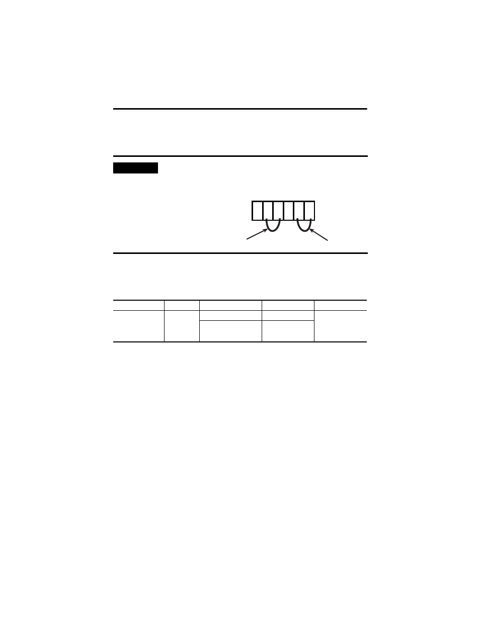
IMPORTANT
Short-circuit unused input channels to the reference pole by
connecting wire jumpers.
Input Channels
Polarity
Current or Voltage
Range
Safety Accuracy
8
unipolar
0…+10V
0…2000
2%
0…20 mA / 4…20 mA
0…1000
(1)
0…2000
(2)
(1)
with external 250
Ω shunt
(2)
with external 500
Ω shunt
AI
T1 I1 L- T2 I2 L-
1
2
3
4
5
6
wire jumpers
wire jumpers